HS50_advance_level 2.pdf - 第329页
Stud ent Gu ide HS-5 0 Adva nced II 07/2 002 Ed ition 11 DP-Axis 7 (1) T urning s tation / DLM1 (2) M3 x 25 hexag on so cket-he ad sc rew (3) Back part of the colle ct&place he ad )LWWLQJW KHWXUQLQJV W D…
07/2002 Edition Student Guide HS-50 Advanced II
11 DP-Axis
6
5HSODFLQJVSDUHSDUWV
5HSODFLQJWKHWXUQLQJVWDWLRQ
7RROVDQGHTXLSPHQW
– Set of DIN 911 Allen keys
– SITEST program
3DUWV
Turning station / DLM1, item no. 00341780-01
'LVPDQWOLQJWKHWXUQLQJVWDWLRQ
➠ Switch the placement system off and secure it to prevent switching on.
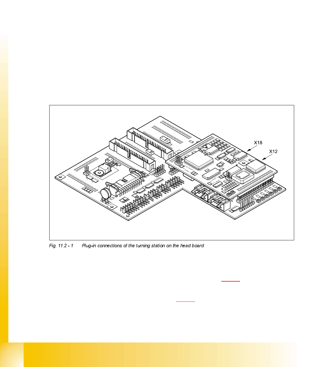
➠ Remove the plugs from sockets X12 and X18 on the head board.
➠ Push the collect&place head until it reaches the stopper on the deflection roller of the X-axis
toothed belt.
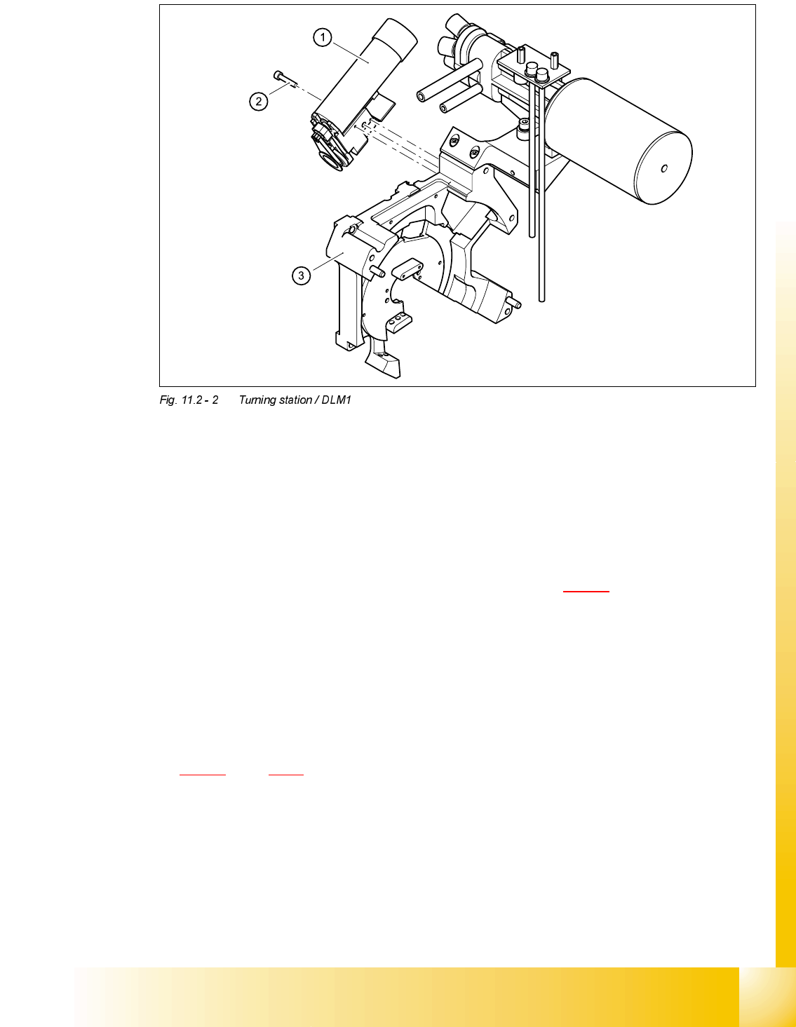
➠ Undo the M3x25 hexagon socket-head screw (see item 2 in Fig. 11.2 - 2) on the rear panel of
the back part.
➠ Carefully pull the turning station (item 1 in Fig. 11.2 - 2) back and remove.
Student Guide HS-50 Advanced II 07/2002 Edition
11 DP-Axis
7
(1) Turning station / DLM1
(2) M3x25 hexagon socket-head screw
(3) Back part of the collect&place head
)LWWLQJWKHWXUQLQJVWDWLRQ
➠ Make sure that the contact surfaces of the turning station and rear panel are clean.
➠ Insert the M3 x 25 hexagon socket-head screw (item 2 in Fig. 11.2 - 1) into the hole in the
centering station.
➠ Run the cable between the vacuum hose and the vacuum generation socket.
➠ Place the holes in the turning station on the parallel pins.
➠ Carefully push the turning station towards the back part until it reaches the stop.
➠ Fix the turning station with the hexagon socket-head screw.
➠ Plug the cable into sockets X12 and X18 on the head board (see item X12 and X18 in Fig.
11.2 - 1
, page 11 - 6.
6HWWLQJV
➠ Switch the placement system on and start it up.
➠ Use the SITEST program to run a function test.
07/2002 Edition Student Guide HS-50 Advanced II
11 DP-Axis
8
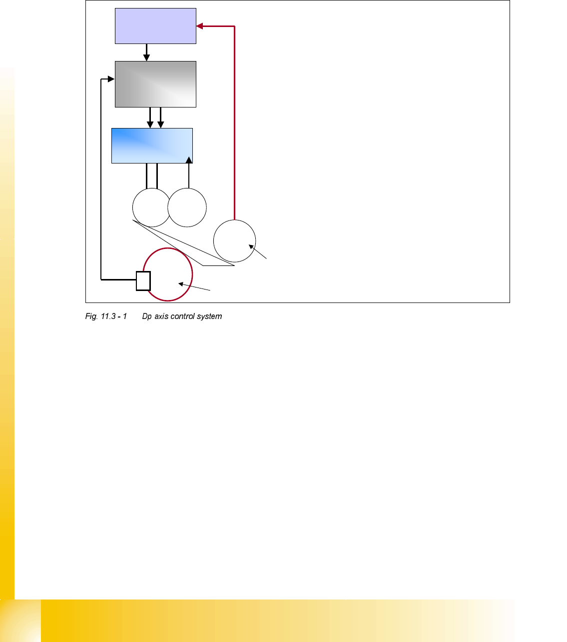
'3$[LVFRQWURORYHUYLHZ
%DVLF&RPSRQHQWVRIWKH'3D[LVGULYH
6WHSSHU0RWRU&RQWURO3ULQFLSOH
The stepper motor, which acts to swivel out the drive O-ring to engage with the segment sleeve,
is controlled and monitored by the Machine Controller via the CANBUS. When the Star axis is in
position, and the axis ’End Signal’ is sent to the Machine Controller, the Machine Controller gives
the command to swivel out. The stepper motor rotates 90° to engage with the sleeve, the slotted
light barrier monitors this movement and when it is complete the signal is reported back to the Ma-
chine Controller.
The Machine Controller now sends the 'Servo Enable' command to the Axis Controller and as a
result the drive motor will start and rotate the sleeve to the required position. Once the axis card
measures that the position is correct it then gives the 'End Signal' to the Machine Controller. The
command is then sent to the stepper motor to swivel back the drive system that does so by re-
versing 90° back to it's home position. Again when this movement is complete the signal is sent
back to the Machine Controller.
These functions can be tested using the 'Single Funtions' tests in the SITEST program.
½ The Dp swivel motor is controlled by
the machine controller via the
CANBUS.
½ The swivel motor position is detected
by a slotted light barrier which monitor
the disk fitted to the motor shaft.
½ The axis controller is enabled with the
“swiveled in signal”sent to the machine
controller via the CANBUS.
½ The axis controller is disabled with the
“swiveled off signal”sent to the machine
controller via the CANBUS.
½ The position is directly measured on
the sleeve by the encoder looking at the
scale.
Axis
controller
Servo
amplifier
A/B
M
=
G
=
M
∏
Encoder system using scale on rear
of sleeve.
Machine
controller
Swivel Stepper Motor
CANBUS feedback to
MC from Swivel motor.