HS50_advance_level 2.pdf - 第334页
07/2002 Editio n Student G uide HS -50 Advanc ed II 11 DP-Axis 12 ; = z-axis ; = star - axis ; = dp - axis 3LQDVVLJQ PHQW 7 H VW6 HWX S NOTE At prese nt, there i s no mea suring adapter av ailabl…
Student Guide HS-50 Advanced II 07/2002 Edition
11 DP-Axis
11
&KHFNLQJWKHWUDFNVLJQDOV
7HVWLQJ7RROV
– One 2-channel storage oscilloscope > 20 MHz
– Test pins 1.4 mm, 1.5 mm and 1.6 mm
2YHUYLHZ
'LJLWDO7UDFN6LJQDOVRIWKH+HDG$[HV
0HDVXUHPHQWRIWKH7UDFN6LJQDOVRI6WDU=DQG'3$[HVDWWKH,QWHUPHGLDWH'LVWULEXWRU
63
$[HV $GMXVWPHQW 2VFLOORVFRSH'LVSOD\
star none pulse signal amplitude 3.6V
ss
z none pulse signal amplitude 3.6V
ss
dp read head on 1.5 mm,
parallel to glass pane
pulse signal amplitude 3.6V
ss
07/2002 Edition Student Guide HS-50 Advanced II
11 DP-Axis
12
; = z-axis
; = star - axis
; = dp - axis
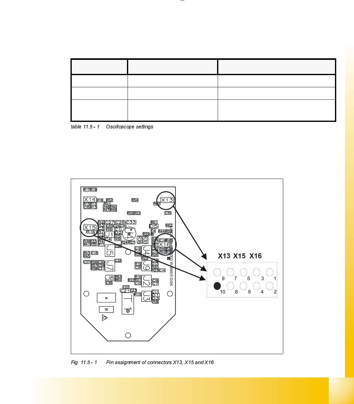
3LQDVVLJQPHQW
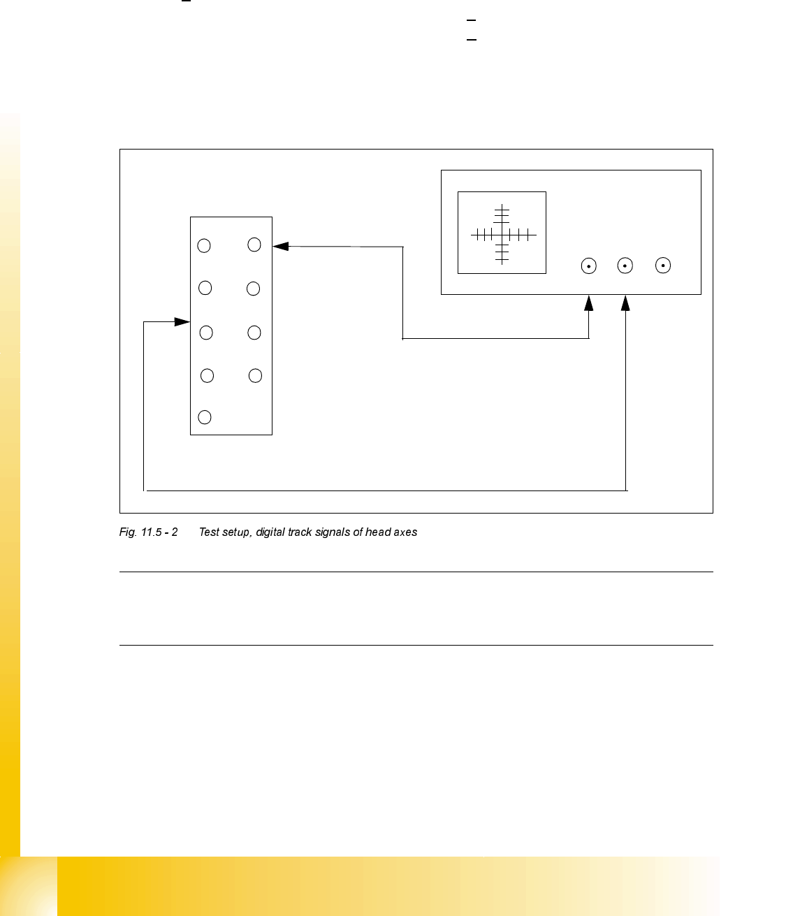
7HVW6HWXS
NOTE
At present, there is no measuring adapter available. Therefore, the track signals can only be
measured on the pins.
1. Ground 2. Track A
3. Track A
4. Ground
5. Track B 6. Track B
7. Track N 8. Track N
9. -4V 10.removed
12
3
4
5
6
78
9
10
X
CH1
CH2
EXT
X13 / X15 / X16
Student Guide HS-50 Advanced II 07/2002 Edition
11 DP-Axis
13
2VFLOORVFRSH6HWWLQJV
3URFHGXUH
➠ Turn on the machine.
➠ Connect both channels to the connectors X13, X15 or X16, pin1 respectively.
➠ Set the oscilloscope to "auto" (with trigger).
➠ With the help of the positioning switches of CH1 and CH2, move the oscilloscope ray of CH1
to the center of the screen and the oscilloscope ray of CH2 to the lower edge of the screen.
➠ Change the connection of CH1 to connector X13, X15 or X16 on pin 2 respectively.
➠ Change the connection of CH2 to connector X 13, X15 or X16 on pin 5 respectively.
➠ Set the trigger to "norm" and set the oscilloscope with "trigger" to a suitable triggering
threshold.
➠ Manually, move the appropriate axis back and forth.
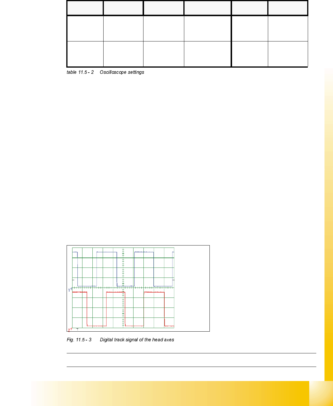
– If you adjusted the read correctly, the following illustration will be displayed on the
oscilloscope screen:
NOTE:Pulse width is dependent on the speed, the phase location is dependent on the direction.
&KDQQHO 6LJQDO &RXSOLQJ <'HIOHFWLRQ &KDQQHO 6LJQDO
CH1
track A of X13,
X15 o r X16,
pin 2 resp.
DC 1.0 V / DIV CH1
track A of X13,
X15 o r X16,
pin 2 resp.
CH2
track B of X13,
X15 or X16 pin
5 resp.
DC 1.0 V/ DIV CH2
track B of X13,
X15 or X16 pin
5 resp.
Spur A / track A
Spur B / track B