HS50_advance_level 2.pdf - 第339页
Stud ent Gu ide HS-5 0 Adva nced II 07/2 002 Ed ition 11 DP-Axis 17 0 HDVX UHPH QW6 HWXS IRU $ [ LV$ GMX VWPH QWV ready for operat ion enable outp ut stage effecti ve current lim it error tac ho P-gain axis …
07/2002 Edition Student Guide HS-50 Advanced II
11 DP-Axis
16
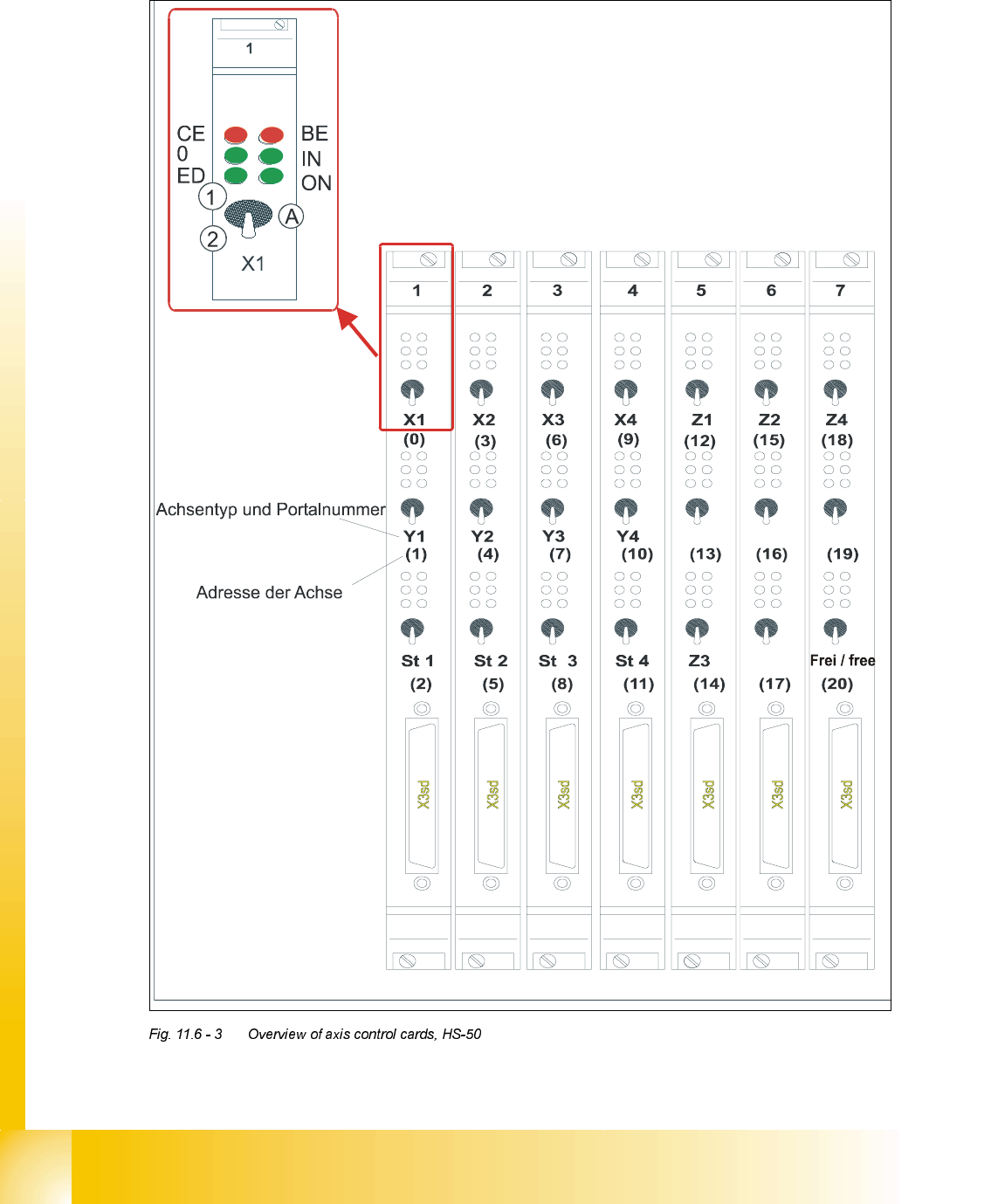
2YHUYLHZRI$[HV&RQWURO&DUGV+6
type of axis and gantry number
adress of axis
'3 '3
'3
'3
CE = Counting error
0 = Zero pulse
ED = End signal
BE = General error, module error
IN = Initialized
ON = Servo ON
(A) Axis enable switch
(1) Servo ON
(2) Servo OFF
Student Guide HS-50 Advanced II 07/2002 Edition
11 DP-Axis
17
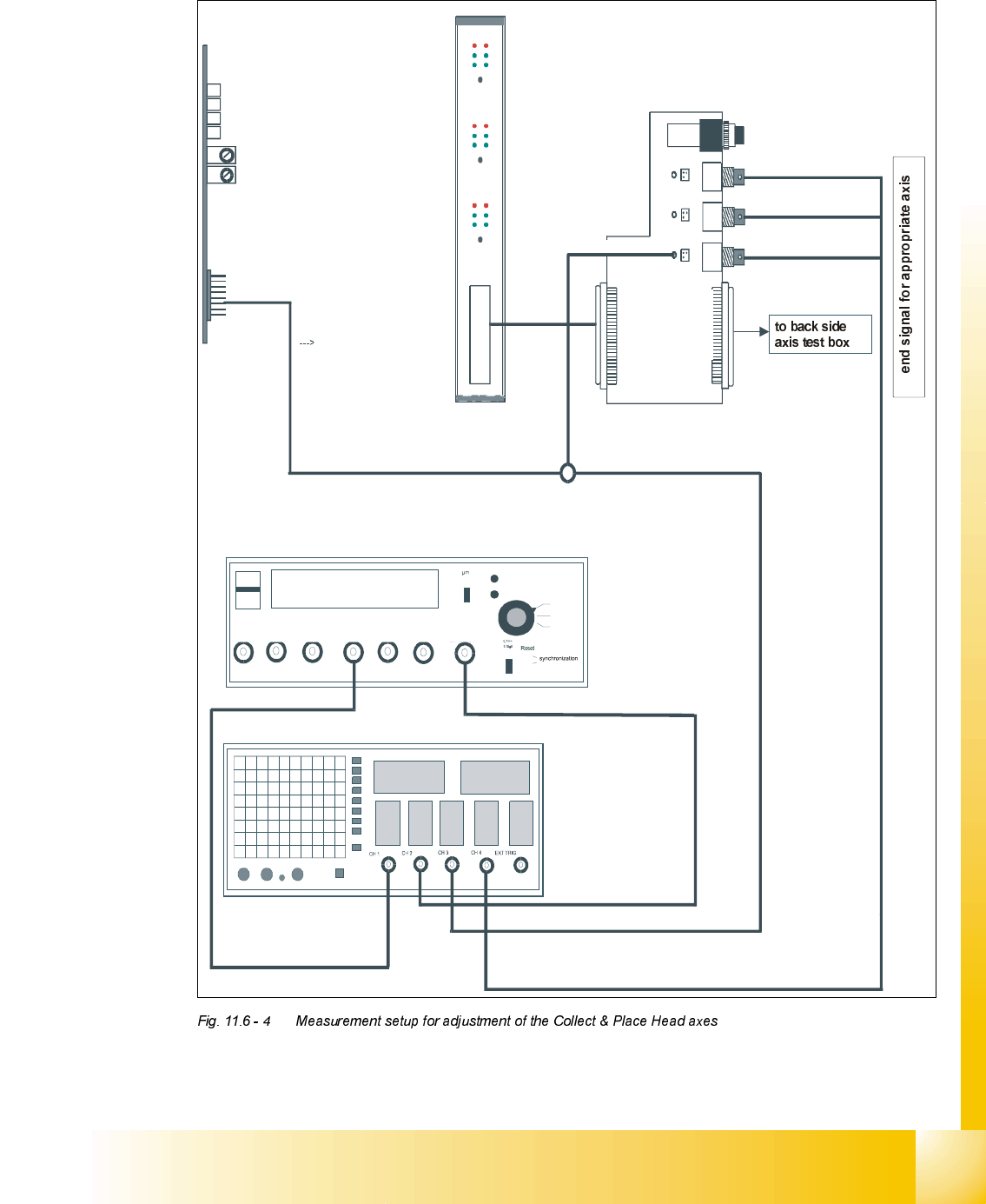
0HDVXUHPHQW6HWXSIRU$[LV$GMXVWPHQWV
ready for operation
enable output stage
effective current limit
error
tacho
P-gain
axis 0
axis 1
axis 2
measuring current of star - axis
changeover switch pressed down
end signal axis 0
end signal axis 1
end signal axis 2
interface
test adapter
axis test box
actual current
with RC - filter
current measuring of dp - axis and z-axis only
interface axis control card
interface axis tes
t box
track A track B zero pulse Vnom force end signal deviat. of pos.
dgt
zero pulse
end signal
axis 0
axis 1
axis 2
OFF
ON
Vnominal
d
e
v
i
a
t
i
o
n
o
f
p
o
s
i
t
i
o
n
c
u
r
r
e
n
t
v
a
l
u
e
e
n
d
s
i
g
n
a
l

07/2002 Edition Student Guide HS-50 Advanced II
11 DP-Axis
18
'S$[LV
*HQHUDO3UHSDUDWLRQV
➠ Start SITEST.
➠ Turn on the compressed air supply.
➠ Prepare the measurement setup for the star-axis acoording to .
➠ Set the oscilloscope according to the table below.
➠ Perform a head reference run.
NOTE
Use an RC - filter to record the current curve
In order to measure the actual current on the servo amplifier, connect only the actual current and
no *1'.
Measure the end signal on the measuring adapter of the axis control card, with the switch
activated.
(IIHFWVRI3*DLQ6HW7RR+LJKRU7RR/RZ
NOTE
If the P-gain is set too low, the deviation of position will sag and the end signal will be prolonged.
If the actual current is set too high, the end signal will be prolonged as well, the actual current and
the deviation of position will oscillate however.
$GMXVWPHQWRI7DFKRWR9
6,7(67
➠ Select "C&P Heads" ==> "Select head ==>
"Axis functions" ==> "Select dp - axis" ==> "Tacho adjustment".
➠ Use the potentiometer "Tacho" on the servo board to adjust the displayed value on the station
monitor to 0V +/- 10 mV.