HS50_advance_level 2.pdf - 第350页
S tudent Guide HS-50 Ad vanced II 12 S pecial handlin g for th e Z-axis Edition 0 7/2002 6 7 UDYHOS URILOHZ KHQSLFNLQJ XS %DVLFLQIRU PDWLRQ The up and do wn positi oning ty pes for the Z- axis ca n be p rogr…
Student Guide HS-50 Advanced II
Edition 07/2002 12 Special handling for the Z-axis
5
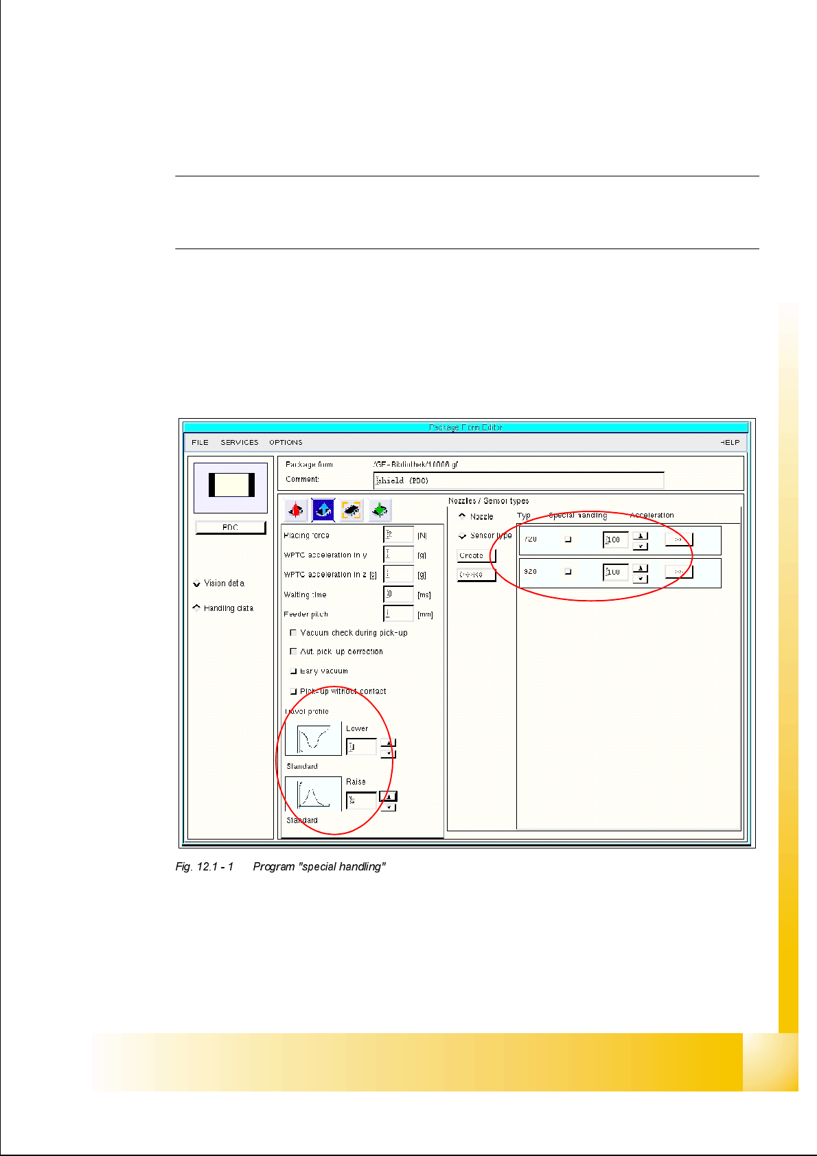
6SHFLDOKDQGOLQJIRUWKH=D[LV
Note:
All following travel profiles from the Z-axis appears in the trapezoidal mode (HS-50).
With the option upgrade to HS-50+ and at the HS-55 machine move the Z-axis in the sine mode.
3URJUDP6SHFLDOKDQGOLQJFRQFHUQLQJWKH6RIW
ZDUHYHUVLRQ
Special handling for 4XX/501/502 station SW with reduced acceleration Z-Axis (99% S25HM
/ 88% S20) (change at 503 station SW only the acceleration/deceleration slope)
Special handling 503 station SW with this special programming of Z-Axis-mode.
Student Guide HS-50 Advanced II
12 Special handling for the Z-axis Edition 07/2002
6
7UDYHOSURILOHZKHQSLFNLQJXS
%DVLFLQIRUPDWLRQ
The up and down positioning types for the Z-axis can be programmed separately. The positioning
types do not affect each other and can be combined as desired. Naturally there are combinations
that do not make any sense and take a lot of time.
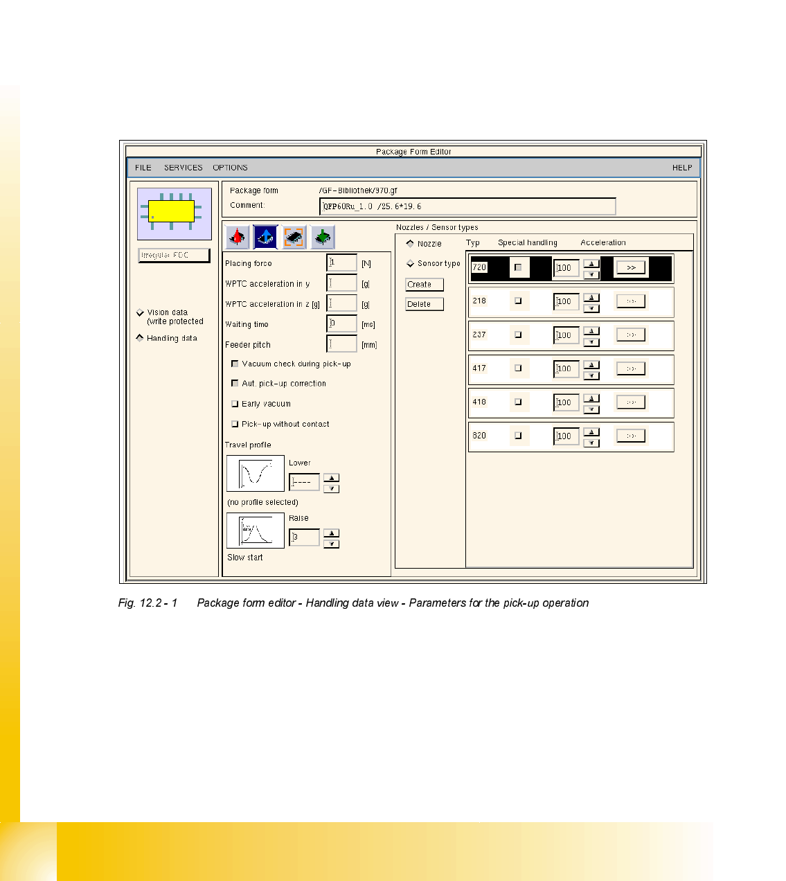
2YHUYLHZDQGSURJUDPLQJWKHWUDYHOSURILOHVZKHQSLFNXS

Student Guide HS-50 Advanced II
Edition 07/2002 12 Special handling for the Z-axis
7
%ULHIGHVFULSWLRQRIWKHKDQGOLQJGDWDIRUWKHSLFNXSRSHUDWLRQ
3ODFLQJIRUFH
This is the placement force applied to the component when picking up a component from the
feeder and is measured using the motor current. (Not active, the placement force must be
minimal).
:37&DFFHOHUDWLRQLQ\]
The acceleration for the corresponding axis can be reduced for y (MTC feed axis) and z (MTC
lifting axis).
:DLWLQJWLPH
The time that the Z-axis waits when picking up the component from the component surface in
order to guarantee 100% safety when picking up critical and possibly expensive components.
)HHGHUSLWFK
The distance between 2 components on the tape. This value is required along with traceability and
the splice detector to calculate the fill level to determine when a new component reel is needed.
&DXWLRQ
The entry for the feeder pitch value has priority 2 in the package form editor!!! The traceability
option assigns the entry for the feeder pitch value priority 1 in the component editor.
9DFXXPFKHFNGXULQJSLFNXS
A check is conducted on the vacuum after picking up a component. The vacuum check is
automatically deactivated for 0201 placement and when nozzles of type 906/706 are used.
$XWSLFNXSFRUUHFWLRQ
The pick-up position correction from the feeder is automatically calculated from the component
position of the nozzle.
1RWH
In previous software versions the automatic pickup correction was enabled and disabled with the
"Cubic Component" radio button. The "Cubic Component" radio button now manipulates just the
image scale for the Vision system.