HS50_advance_level 2.pdf - 第364页
S tudent Guide HS-50 Ad vanced II 12 S pecial handlin g for th e Z-axis Edition 0 7/2002 20 %ULHIGHV FULSWLRQRIWK HKDQGOLQJ GDW DIRUW KHSOD FHPHQWRSHUD WLRQ 3ODFLQJ IRUFH Force, mea sured v ia the cur…
Student Guide HS-50 Advanced II
Edition 07/2002 12 Special handling for the Z-axis
19
7UDYHOSURILOHZKHQSODFLQJ
%DVLFLQIRUPDWLRQ
The up and down positioning types for the Z-axis can be programmed separately. The positioning
types do not affect each other and con be combined as desired. Naturally there are combinations
that do not make any sense and take a lot of time.
2YHUYLHZDQGSURJUDPLQJWKHWUDYHOSURILOHVZKHQSODFHPHQW

Student Guide HS-50 Advanced II
12 Special handling for the Z-axis Edition 07/2002
20
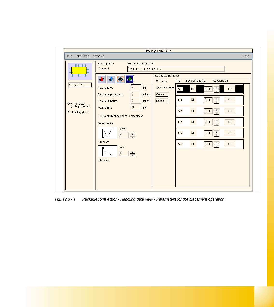
%ULHIGHVFULSWLRQRIWKHKDQGOLQJGDWDIRUWKHSODFHPHQWRSHUDWLRQ
3ODFLQJIRUFH
Force, measured via the current draw, with which the component is pressed into the soldering
paste. The value for the placing force is only active for certain Z-axis travel profiles.
%ODVWDLUISODFHPHQW
Here can be specified the starting point for switching off the blast air when placing a component,
as a result the blast pressure on the nozzel is influenced.(see 6.4.3 Blast air control)
%ODVWDLUIUHWXUQ
Here can be specified the starting point for switching off the blast air when returning a component
(MTC), as a result the blast pressure on the nozzel is influenced.(see 6.4.3 Blast air control)
:DLWLQJWLPH
The wait time is the time that the Z-axis waits on the surface of the component when placing the
component in order to ensure safe and accurate placement when travel profile modes are used
for the Z-axis.
9DFXXPFKHFNSULRUWRSODFHPHQW
A check is conducted on the vacuum before placing a component. The vacuum check is
automatically deactivated for 0201 placement and when nozzles of type 906/706 are used.
7UDYHOSURILOH
Different travel profiles can be selected for the up and down motion of the Z-axis.
Student Guide HS-50 Advanced II
Edition 07/2002 12 Special handling for the Z-axis
21
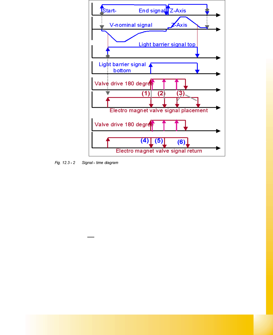
'HVFULSWLRQ%ODVWDLUFRQWURO
Blast air control at placement:
Value “0” mean the blast air valve don‘t switch on.
Value “1-50” mean blast air valve is switched OFF when stepper motor valve drive start to
move.
Value “51-150” mean blast air valve is switched OFF when stepper motor valve drive moved
for 90 degree.
Value. “151-255 mean blast air valve is switched OFF when stepper motor valve drive moved
for 180 degree.2U
at light barrier top.
No value “----” (from converting 501/502 to 503 format) mean same mode than (existing
standard).
Air kiss control at return component! (not reject)
Value and description like
Value and description like
Value. “151-255” mean blast air valve is switched OFF when stepper motor valve drive moved
for 180 degree.