HS50_advance_level 2.pdf - 第366页
S tudent Guide HS-50 Ad vanced II 12 S pecial handlin g for th e Z-axis Edition 0 7/2002 22 7 UDYHOSU RILOHVRI WKH= D[L VZKHQ SODF LQJFRPS RQHQW V On the line co mputers the travel profi le for the up a…
Student Guide HS-50 Advanced II
Edition 07/2002 12 Special handling for the Z-axis
21
'HVFULSWLRQ%ODVWDLUFRQWURO
Blast air control at placement:
Value “0” mean the blast air valve don‘t switch on.
Value “1-50” mean blast air valve is switched OFF when stepper motor valve drive start to
move.
Value “51-150” mean blast air valve is switched OFF when stepper motor valve drive moved
for 90 degree.
Value. “151-255 mean blast air valve is switched OFF when stepper motor valve drive moved
for 180 degree.2U
at light barrier top.
No value “----” (from converting 501/502 to 503 format) mean same mode than (existing
standard).
Air kiss control at return component! (not reject)
Value and description like
Value and description like
Value. “151-255” mean blast air valve is switched OFF when stepper motor valve drive moved
for 180 degree.

Student Guide HS-50 Advanced II
12 Special handling for the Z-axis Edition 07/2002
22
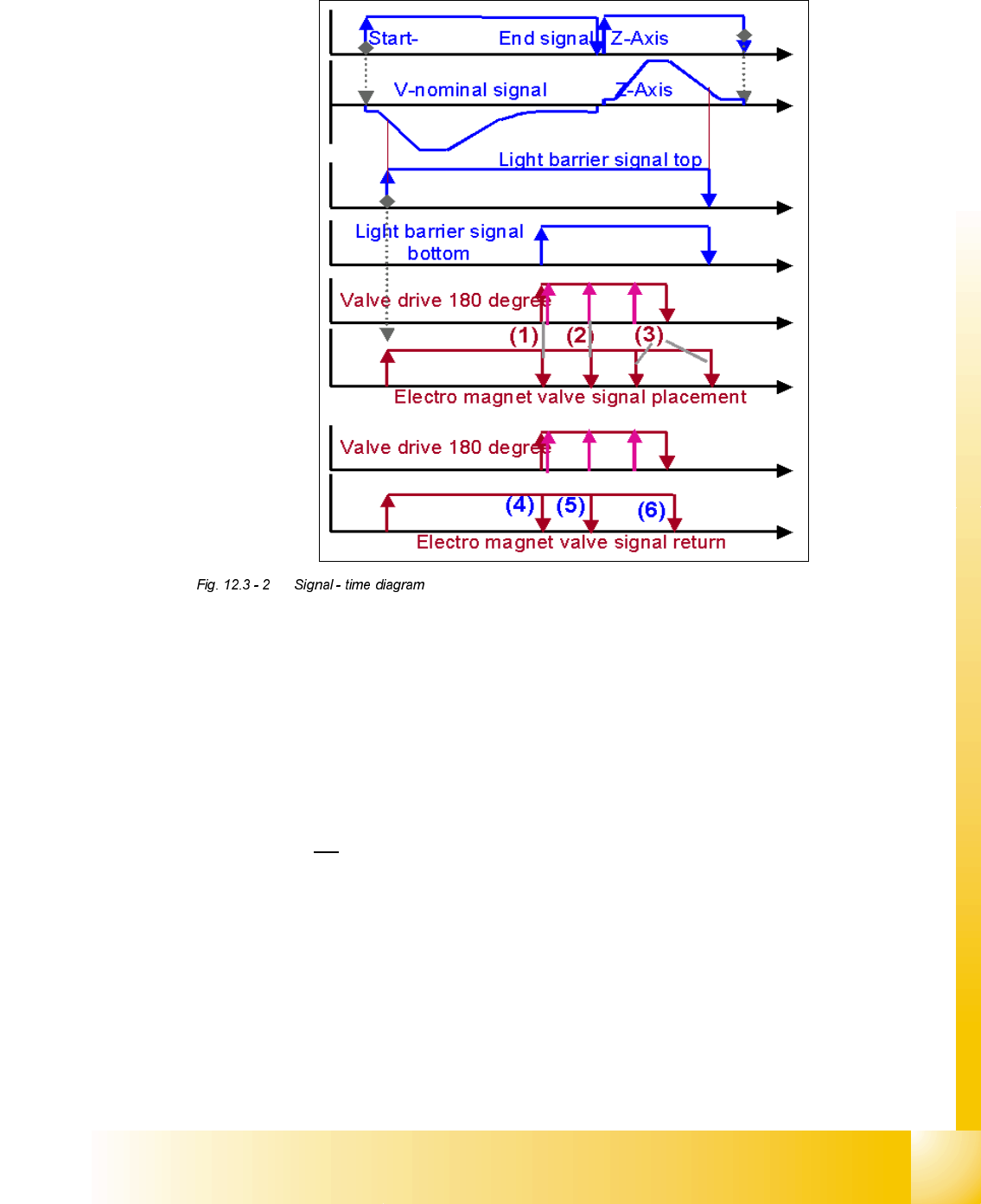
7UDYHOSURILOHVRIWKH=D[LVZKHQSODFLQJFRPSRQHQWV
On the line computers the travel profile for the up and down motion of the Z-axis can be specified
for the placement operation for each package form.
1RWH
The travel profile specification also includes the special handling for packs of 8 nozzles, i.e. there
is no differentiation between nozzle types anymore on the MC.
=D[LVWUDYHOSURILOHGRZQZDUGVRQSODFHPHQW
0RGHNormal downward motion with light barrier at bottom
0RGHCreep mode and light barrier at bottom.
The Z-axis moves about 1mm before reaching the target position with V
min
and the forced air is
activated when switching the light barrier at the bottom.
0RGHCurrent sensor
The Z-axis moves with the current sensor pointed down, i.e. the Z-axis presses the component
into the soldering paste with the placing force defined.
0RGHCurrent sensor with creep
The Z-axis moves with the current sensor pointed down, and the system switches to V
min
1 mm
before reaching the target position, and the component is pressed into the soldering paste with
the specified placement force.
=D[LVWUDYHOSURILOHXSZDUGVRQSODFHPHQW
0RGHStandard mode
0RGHCreep mode, i.e. the Z-axis moves up slowly the first few millimeters.
Student Guide HS-50 Advanced II
Edition 07/2002 12 Special handling for the Z-axis
23
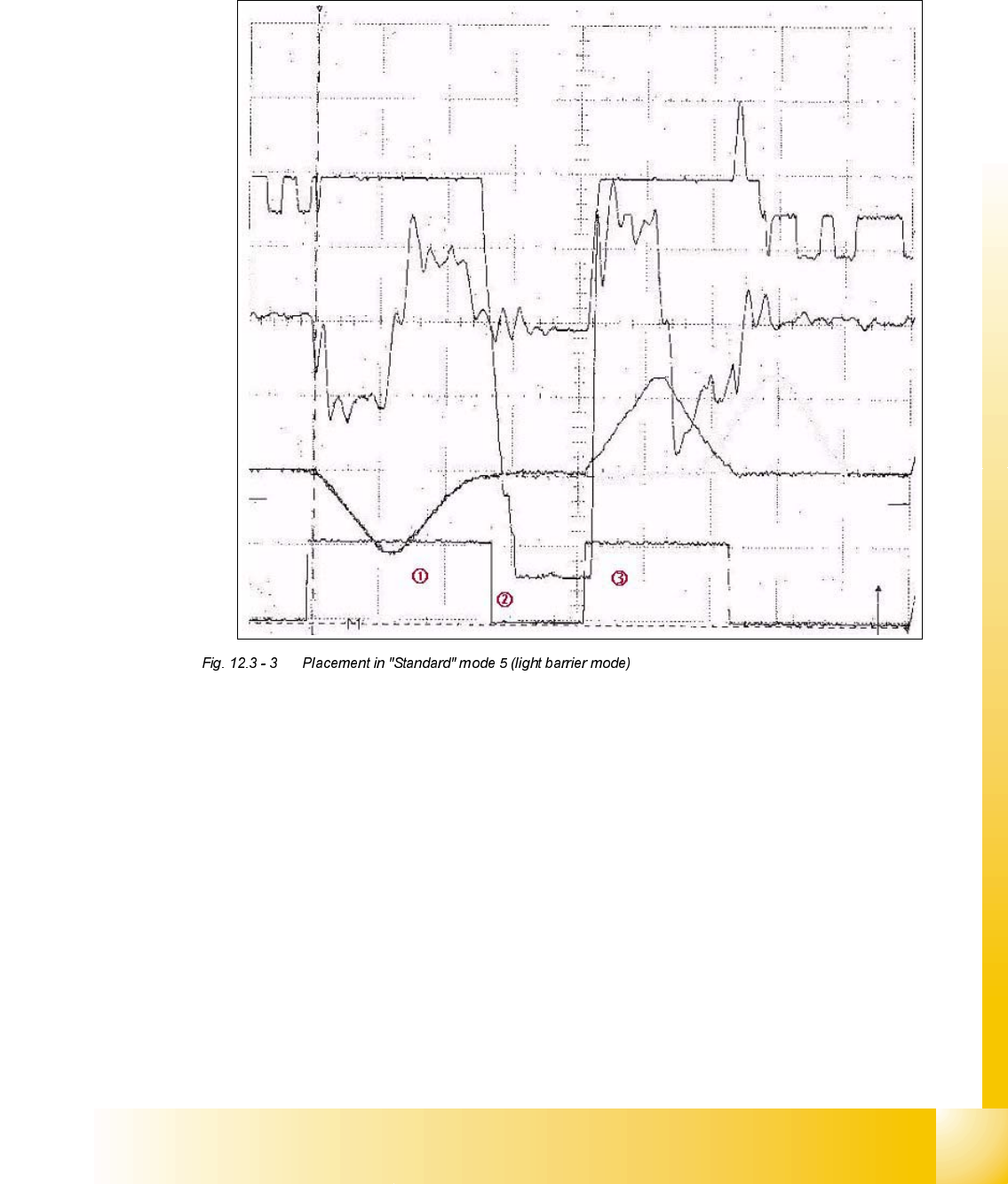
7UDYHOSURILOHVLQGHWDLO
3ODFLQJDFRPSRQHQWLQ6WDQGDUGPRGHOLJKWEDUULHUPRGH
6LJQDOVIURPWRSWRERWWRP
Positional deviation: 200 mV 10 ms
Iactual: 5 V 10 ms
Vtarget: 5 V 10 ms
End signal: 5 V 10 ms
about 28 ms Position when moving down to place the component
on the 12th PCB.
about 12 ms Time on the component to switch on the forced air plus
the system’s reaction time
about 21 ms Position while moving down