HS50_advance_level 2.pdf - 第371页
S tudent Guide HS-50 Adva nced II Editio n 07/200 2 12 S pecial handlin g for th e Z-axis 27 6LJ QDOVIURP WRSWR ERWWRP Placem ent force of 5N Positio nal de viation: 2 00 mV 10 ms For ce si gnal : 5 V 10 ms…
Student Guide HS-50 Advanced II
12 Special handling for the Z-axis Edition 07/2002
26
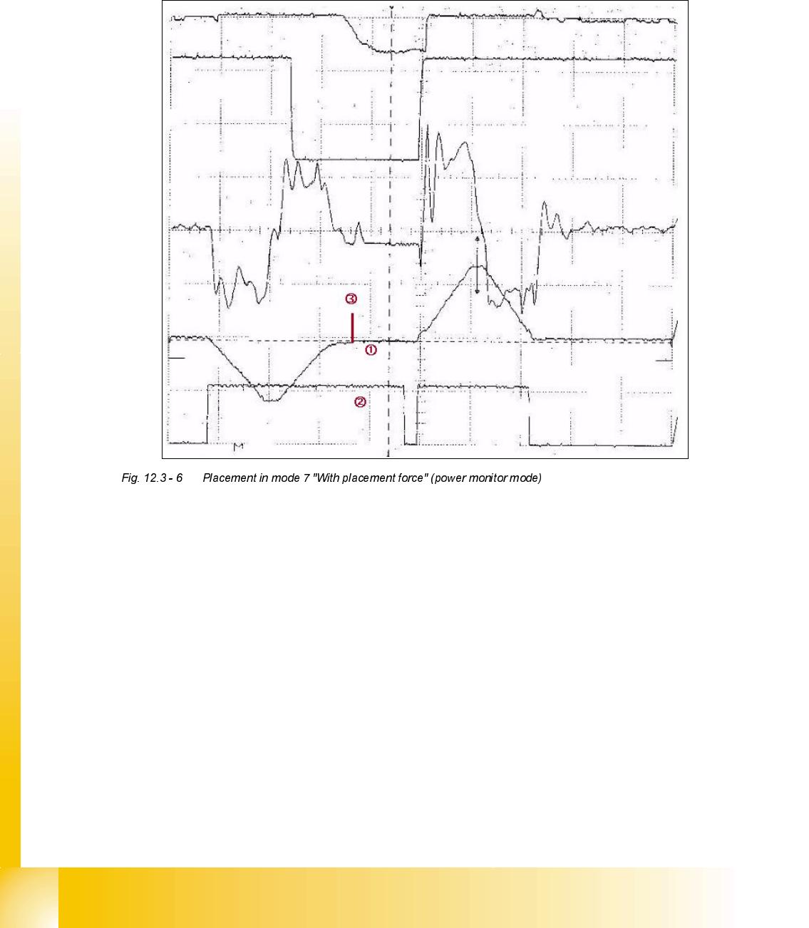
3ODFHPHQWLQPRGH:LWKSODFHPHQWIRUFHSRZHUPRQLWRUPRGH
The component is to be placed on the circuit board with more than 2 N of placement force. The
mode for the downward motion and the value for the placement force must always be set. The
placement operation is delayed until the current in the servo-amplifier has built up.
6LJQDOVIURPWRSWRERWWRP Placement force of 3N
Positional deviation: 200 mV 10 ms
Force signal: 5 V 10 ms
Iactual: 5 V 10 ms
Vtarget: 5 V 10 ms
End signal from the oscilloscope memory
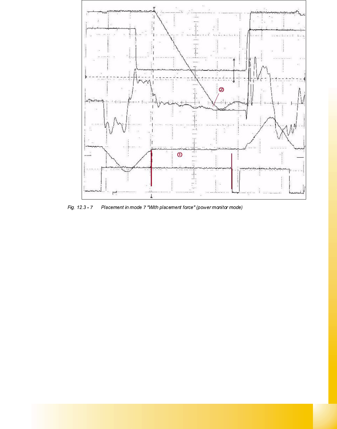
Mode 2 "With placement force" (power monitor mode) was used for placement in order to increase
the placement force to 3 N.
The end signal is delayed until the corresponding current in the servo-amplifier has built up.
Forced air is switched on during this extended positioning time.
Activation time for the bottom light barrier
Student Guide HS-50 Advanced II
Edition 07/2002 12 Special handling for the Z-axis
27
6LJQDOVIURPWRSWRERWWRP Placement force of 5N
Positional deviation: 200 mV 10 ms
Force signal: 5 V 10 ms
Iactual: 5 V 10 ms
Vtarget: 5 V 10 ms
End signal from the oscilloscope memory
Increased positioning time to build up the placing force
Positional deviation that can be measured with the axis firmware on an HS-50/S-25HM when
the power monitor mode is active.
Student Guide HS-50 Advanced II
12 Special handling for the Z-axis Edition 07/2002
28
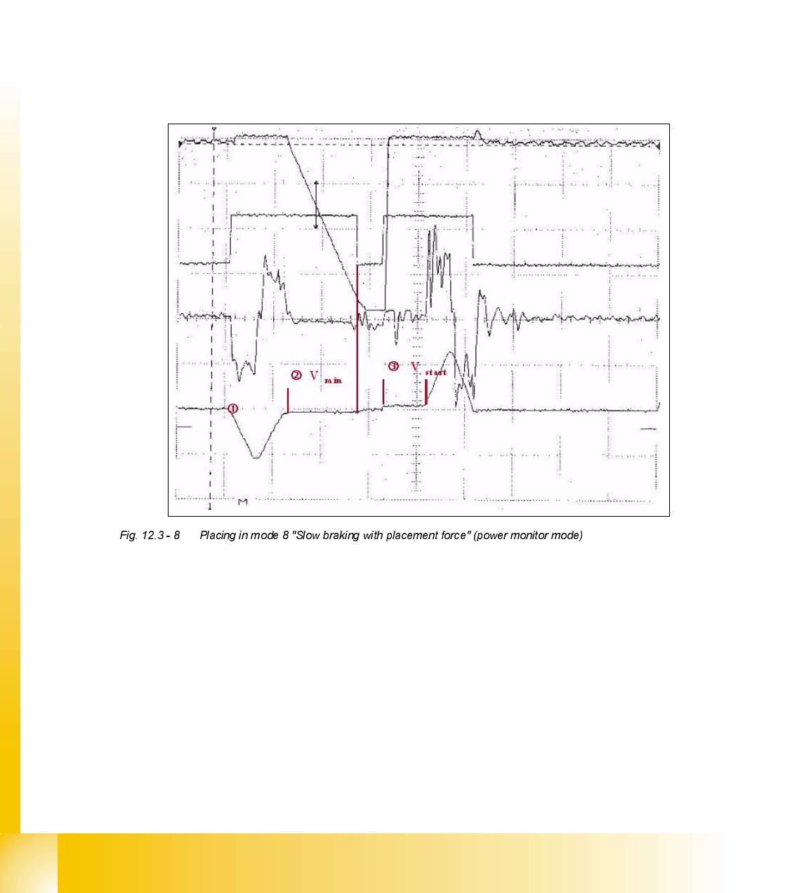
3ODFHPHQWLQPRGH6ORZEUDNLQJZLWKSODFHPHQWIRUFHSRZHUPRQLWRUPRGH
DQGPRGH6ORZVWDUW
Just like for the light barrier mode, the last 44 digits before reaching the placement height are
traversed at minimum speed when moving down in mode 8 "Slow braking with placement force".
This allows the component to be placed correspondingly slowly in the glue or soldering paste,
even when increased placement forces are applied. When moving up in mode 10 "Slow", any
vacuum remaining between the nozzle and the component is released. Travel is also begun at the
start speed for a 44 digit path. Additionally, the acceleration or deceleration of the axis can be
reduced using the special procedure programmed for the nozzle. You must decide yourself if this
is reasonable or not depending on the application. Disadvantage: The placement operation takes
about 55 ms longer (about 35 ms in mode 8 and about 20 ms in mode 10).
6LJQDOVIURPWRSWRERWWRP Placement force of 3N
Positional deviation: 200 mV 20 ms
Iactual: 5 V 20 ms
Vtarget: 5 V 20 ms
End signal: 5 V 20 ms
The standard speed profile is used for positioning in mode 8 "Slow braking with placement
force".
44 digits before reaching the placement height, the axis moves using Vmin.
Begin at the start speed and accelerate to the normal speed profile after traveling for 44 digits