HS50_advance_level 2.pdf - 第385页
Stud ent Gu ide HS-5 0 Adva nced II 07/2 002 Ed ition 14 Conve yor System 11 2YHUY LHZOLI WLQJW DEOH FRQWURO Please se e also circuit dia gramm s fig 2-15, 2-16 and 2-19 Ma i n D i st r i but or X8do GND 24VD C…
07/2002 Edition Student Guide HS-50 Advanced II
14 Conveyor System
10
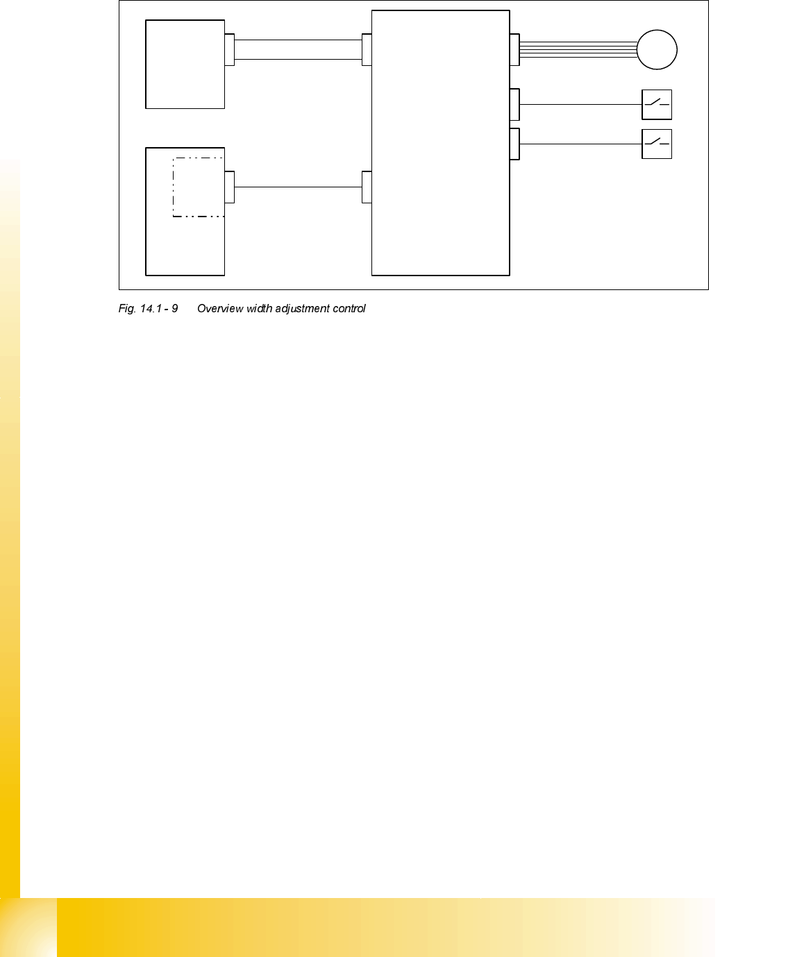
2YHUYLHZZLGWKDGMXVWPHQWFRQWURO
Please see also circuit diagramms fig 2-8, 2-9 and 2-16 and 18
Mai n
Distributor
X8do
GND
24VDC switched
Control
Unit
COM
board
X7to
slow CAN-Bus
Conveyor
Control
X33apX34ap
X3aox12ao
M
x13ao
stepper motor
limit switch
maximum position
limit switch
minimum position
Student Guide HS-50 Advanced II 07/2002 Edition
14 Conveyor System
11
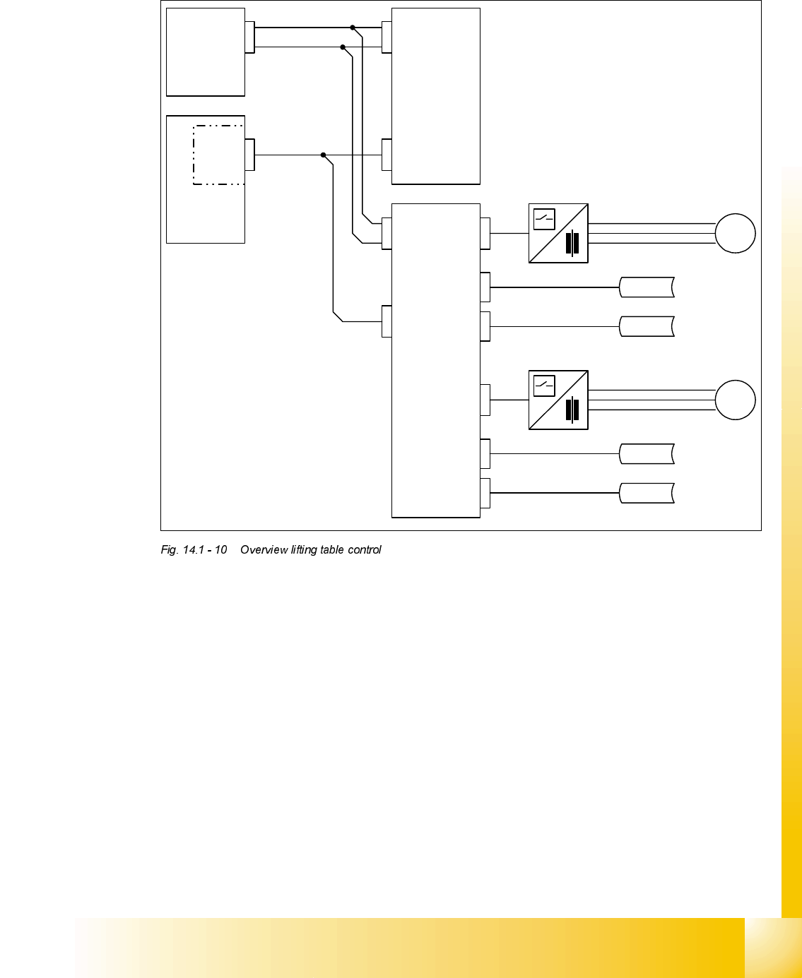
2YHUYLHZOLIWLQJWDEOHFRQWURO
Please see also circuit diagramms fig 2-15, 2-16 and 2-19
Mai n
Distributor
X8do
GND
24VDC switched
Control
Unit
COM
board
X7to
slow CAN-Bus
Conveyor
Control
X33apX34ap
SLIO Modul
X17amX34ap
M
placement area 1
X3amX6am
M
placement area 2
top position
bottom position
sonar bero
sonar bero
X1amX2am
top position
bottom position
sonar bero
sonar bero
X4amX5am

07/2002 Edition Student Guide HS-50 Advanced II
14 Conveyor System
12
2YHUYLHZ
$EEUHYLDWLRQV8VHG
– PCB = Printed Circuit Board
– PCB1 / PCB2 = PCB transport section 1 / 2
– Sonar proximity switch = Ultrasonic sensor (Sensing head incl. amplifier)
– Proximity switch = Inductive proximity switch
&RQVWUXFWLRQDQG)XQFWLRQ
The PCB conveyor system may be designed as a single conveyor (only conveyor 1 is installed)
or as a dual conveyor (see ).
Each conveyor (1 / 2) consists of 5 components:
Input conveyor, conveyor placement area 1(4), intermediate conveyor, conveyor placement
area 2 (3) and output conveyor (see ).
The width of each PCB conveyor system (conveyor 1 and 2) can be adjusted continuously inde-
pendently of the other. The desired PCB conveyor width can be specified in the menu "Width adj.
system". Depending on the speed previously selected (slow / fast), the automatic width adjust-
ment system sets the conveyor width slowly or quickly to the desired width. The range of adjust-
ment for the conveyor width ranges from min. 50 mm and max. 460 mm.
Limit switches limit the possible travel ranges (minimum and maximum).
Triggering a limit switch (input signal turns to 1 briefly) resets the output for the motor of the con-
veyor width adjustment system, i.e., the motor - and thus the movement - is stopped.
Within the conveyor system the PCB is transported on the conveyor toothed belts which are
arranged in pairs and are driven by a d.c. geared motor.
Sonar proximity switches on each conveyor unit monitor the transport section at each conveyor
unit and thus monitor the presence of the PCB.
The stopper in placement areas 1 and 2 (3 and 4) can be extended pneumatically, stopping the
PCB in the exact X-position. The lifting table is then moved up. As a result, the holddown devices
on the fixed and the movable side of the conveyor are moved down, clamping the PCB in place.
Prior to placement the PCB vision system ascertains the exact position of the PCB clamped in
the PCB conveyor. The deviations in position which are ascertained are incorporated into the
placement coordinates.