HS50_advance_level 2.pdf - 第389页
Stud ent Gu ide HS-5 0 Adva nced II 07/2 002 Ed ition 14 Conve yor System 15

07/2002 Edition Student Guide HS-50 Advanced II
14 Conveyor System
14
Key to
A) PCB transport direction B) Input (B1 / B2)
C) Placement area 1 or 2 (C1 / E1) D) Intermediate conveyor (D1 / D2)
E) Placement area 3 or 4 (C2 / E2) F) Output belt (F1 / F2)
G) Travelling direction of width adj. system H) Detail: PCB stopper
I) -------------- J) Detail: Sonar proximity switch mount sensing
head of proximity switch
1 Screws to fasten the conveyor assem-
blies to the slide unit of the conveyor
assemblies and the base unit
(two M5 hexagonal socket head cap
screws for each)
2 Fixed conveyor side, right-hand
(conveyor 1 / 2)
3 Movable conveyor side, left-hand (con-
veyor 1 / 2)
4 Rocking lever (2 levers per conveyor 1 / 2)
5 Stopper pin at top and bottom 6 PCB stopper (per placement area)
7 Conveyor mount 1
(2 each per movable side)
8 Conveyor mount 2
(2 for each fixed side)
9 Mounting plate for PCB handling unit 10 Lifting table plate (2 for each conveyor 1/2)
11 Guide pillars for lifting table plate 12 Proximity switch for the wide adjustment sys-
tem (per movable side)
13 PCB stopper, basic module 14 Cover with inductive proximity switch for
stopper position
15 Solenoid valve to move stopper in and
out
16 Sonar proximity switch for check on presence
of PCB
in placement areas 1 to 4
17 Piston rod 18 Mount for sonar proximity switch
19 Sonar proximity switch for check of PCB
present in input, intermediate and
output conveyor
20 Fasteners for sonar proximity switch mount
2 hexagonal socket head cap screws M3 x20,
using holes 20a or 20b, depending of con-
veyor area
21 Clamping unit for sonar proximity
switches (sensing head): 1 hexagonal
socket head cap screw M3 x 16
22 -----------
Student Guide HS-50 Advanced II 07/2002 Edition
14 Conveyor System
15

07/2002 Edition Student Guide HS-50 Advanced II
14 Conveyor System
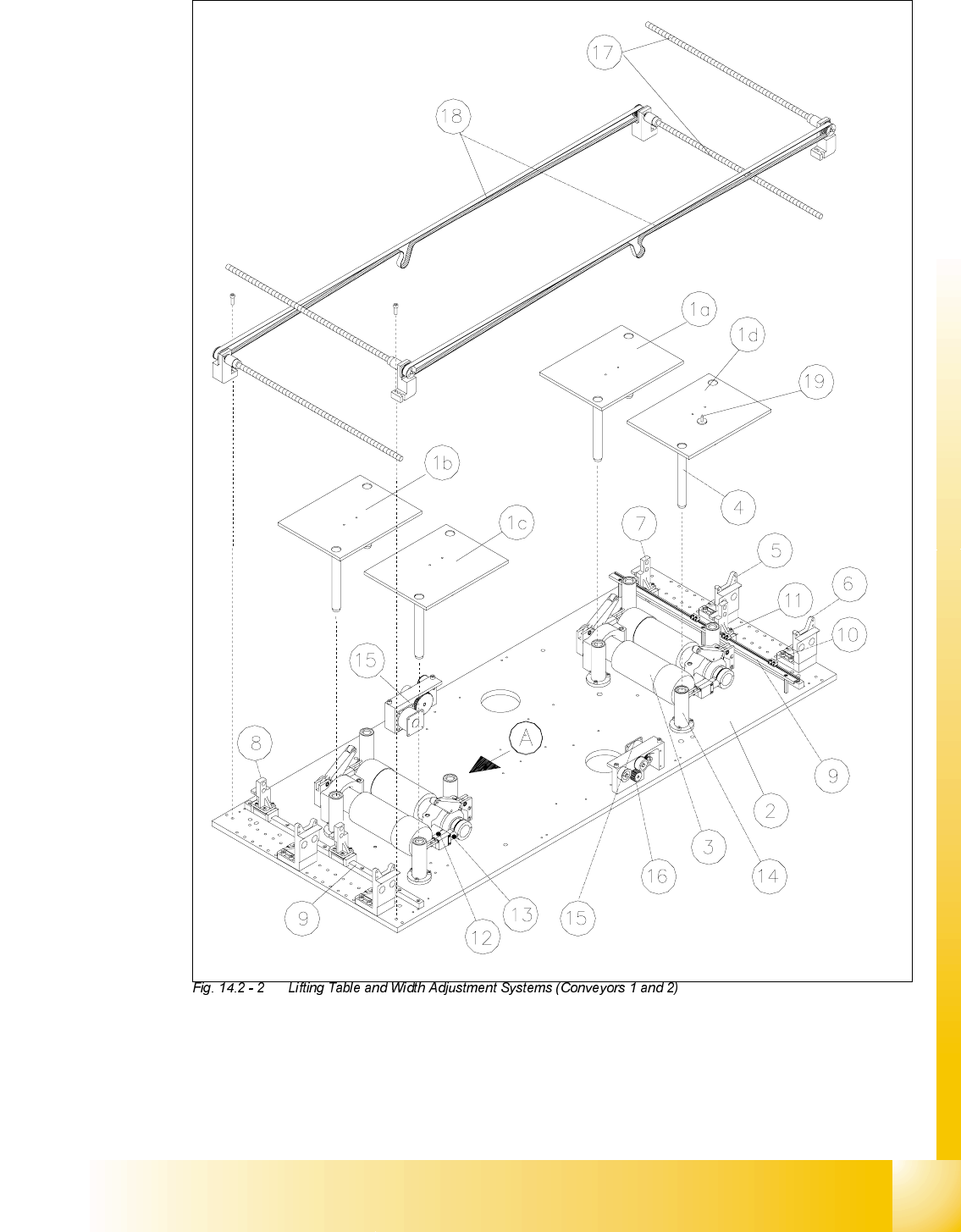
16
Key to
A PCB transport direction
1a - 1d) Lifting table 1 - 4 2) Basic construction of mounting plate
3) Lifting table motor
(2 each per conveyor 1 / 2)
4) Guide pillar
5) Conveyor mount 1 (movable side) 6) Conveyor mount 2 (fixed side)
7) Adapter 1 width adj. system 8) Adapter 2 for width adj. system
9) Linear guide for width adj. system 10) Limit switch, minimum PCB conveyor width
11) Limit switch, maximum PCB conveyor
width
12) Proximity switch "lifting table, down", place-
ment area 1/2
13) Proximity switch "lifting table, up", place-
ment area 1/2
14) Guide tube
15) Drive unit for width adjustment system,
conveyor 1 or 2
16) Toothed belt 10T2.5/245 for
drive for width adj. system
17) Recirculating spindle 18) Synchronizing belt Breco 12 T5/2855
welded
19) PCB support 20) PCB support (for large PCB)