HS50_advance_level 2.pdf - 第408页
07/2002 Editio n Student G uide HS -50 Advanc ed II 14 Conveyor System 34 ➠ Place th e lifting table plate upside do wn on a cl ean, flat s urface. ➠ Carry ou t the steps in the a rea unde r the lifting table plate (e.g.…

Student Guide HS-50 Advanced II 07/2002 Edition
14 Conveyor System
33
➠ If necessary, align the guide rails appropriately.
➠ Remove all tools from the working area of the machine.
➠ Place a PC board in the preceding station or in the PCB input and transport the PCB through
all 5 conveyor areas with the pertinent transport function until it reaches the following station
or the PCB output.
5HPRYLQJDQG,QVWDOOLQJWKH/LIWLQJ7DEOH
CAUTION O
The customer must not loosen screws secured with loctite (e.g., on the screws fastening the guide
pillars of the lifting table). 14
NOTE
The lifting table plate must be removed, for example, in order to exchange hold-down device and
compression spring (see section 14.3.6.1) or to work in the area under the lifting table plate. For
the layout of the lifting table and the lifting table motors, refer to . 14
5HPRYLQJWKH/LIWLQJ7DEOH
➠ Move the conveyor to PD[LPXP width.
➠ Move the Y-gantries into the area outside the PCB conveyor.
➠ Turn off the machine at the main switch and disconnect the machine from the mains.
➠ Conscientiously secure the machine against reactivation during servicing work.
➠ In the pertinent conveyor area, on the fixed DQGthe movable conveyor side, slightly loosen the
M3 set screw on the ball bearing of each rocking lever (see Fig. 14.3.4).
➠ Being careful not to lose the set screw, remove the two ball bearings.
WARNING OO
During the subsequent lifting of the lifting table plate there is a risk of body members being
pinched, crushed or cut off, e.g., between the outer edges of the lifting table plate and the con-
veyor assemblies. 14
➠ Holding the lifting table plate with both hands, lift it up YHUWLFDOO\(see ).
➠ Make certain the lifting table is not tilted while being lifted, otherwise the guide pillars could be
bent in the process.
CAUTION O
Do not place the lifting table plate on its side and do not support it on the guide pillars. 14

07/2002 Edition Student Guide HS-50 Advanced II
14 Conveyor System
34
➠ Place the lifting table plate upside down on a clean, flat surface.
➠ Carry out the steps in the area under the lifting table plate (e.g., exchange the proximity switch
for the motor or the lifting table or the limit switch for min./max. conveyor width as described in
the pertinent section below.
,QVWDOOLQJWKH/LIWLQJ7DEOH
WARNING OO
During the subsequent installation of the lifting table plate there is a risk of body members being
pinched, crushed or cut off, e.g., between the outer edges of the lifting table plate and the con-
veyor assemblies. 14
➠ Make certain that the WUDQVPLVVLRQOHYHU on the pertinent lifting table motor is folded down on
the lifting curve (see Fig. 14.3.5, illustration bottom left).
➠ Holding the lifting table ZLWKERWKKDQGV, place itinto the guiding tubes with the guide pillars
YHUWLFDO (see ).
➠ Let the lifting table plate slowly side down.
➠ Check whether the lifting table plate is FRPSOHWHO\ seated on the lifting curve.
➠ Install the pertinent ball bearing on the rocking levers (see Fig. 14.3.4).
Student Guide HS-50 Advanced II 07/2002 Edition
14 Conveyor System
35
([FKDQJLQJWKH/LIWLQJ7DEOH0RWRUDQGRUWKH6SURFNHW:KHHO
5HPRYLQJWKH/LIWLQJ7DEOH0RWRU6SURFNHW:KHHO
➠ Remove the lifting table as described in section 14.3.8.1.
14
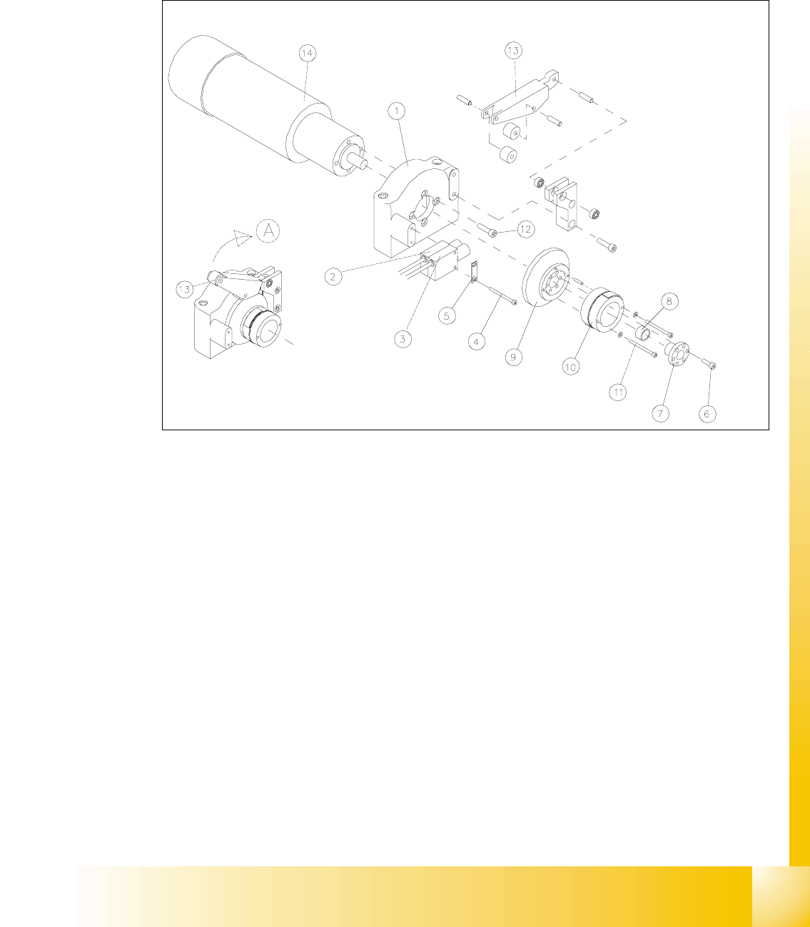
Fig. 14.3.5 Removing the LiftingTable Motor and / or the Lifting Table Proximity Switch
Key to Fig. 14.3.5
A) Fold the transmission lever XS
1) Motor mount 2) Proximity switch "lifting table GRZQ"
3) Proximity switch "lifting table XS 4) Screws fastening the proximity switch :
2 hexagonal socket head cap screws M3 x
30
5) Reinforcement plate for proximity switch 6) Fasteners for clamping flange:
6 hexagonal socket head cap screws
M4x12
7) Clamping flange 8) Annular spring
9) Cam body 10) Sprocket wheel with lead tapes
11) Screws fastening the "sprocket wheel with
lead tapes": 2 hexagonal socket head cap
screws M 3 x 30 with 2 adjusting shims
12) Motor moiunt: 4 hexagonal socket head
cap screws M5 x 12
13) Transmission lever 14) Motor for lifting table 1, 2, 3 or 4