HS50_advance_level 2.pdf - 第414页
07/2002 Editio n Student G uide HS -50 Advanc ed II 14 Conveyor System 40 Fig. 14.3.7 Removing the Dr ive Unit of the Width Adjust ment Sys tem: Short T oot hed Belt Removing the T oothed Belt of Width Adj. System: Loose…

Student Guide HS-50 Advanced II 07/2002 Edition
14 Conveyor System
39
Key to Fig. 14.3.6
,QVWDOOLQJD7RRWKHG%HOWIRUWKH:LGWK$GMXVWPHQW6\VWHP/RQJ
CAUTION O
The new toothed belt is not to be stretched or kinked. 14
➠ Place the new toothed belt (synchronizing belt BRECO) on the two synchronizing disks on the
recirculating spindles and weave the belt in via the deflection pulleys on the drive unit.
➠ Place tension on the toothed belt on the eccentric axis (see Fig. 14.3.7 -> 2) of the "Drive unit
for the width adjustment system" until it reliably engages in the teeth of the synchronizing disk.
Check: The entire width of the toothed belt must be engaged with the synchronizing disk.
and it must be in contact with the circumference of the deflection pulleys on its entire width.
➠ Remove all tools, etc., in the working area of the machine.
➠ Make certain that the transmission lever on the lifting table motor mount is folded onto the lift-
ing curve (see Fig. 14.3.5, illustration bottom left).
➠ Re-install the lifting table as described in section 14.3.8.2.
➠ Carry out the )LQDOVWHSVLQFOIXQFWLRQFKHFN (see section 14.4).
During the function check, move the conveyor to its maximum and minimum width.
([FKDQJLQJD7RRWKHG%HOWIRUWKH'ULYHRIWKH:LGWK$GMXVWPHQW6\VWHP
6KRUW
5HPRYLQJWKH7RRWKHG%HOW'ULYHIRUWKH:LGWK$GMXVWPHQW6\VWHP6KRUW
An overview of the layout of the "Drive unit for the width adjustment system" in conveyor 1 and 2
is shown in . 14
A) PCB transport direction
1) Bearing housing, width adj. system
conveyor 1 or 2
2) Toothed belt width adj. system:
Synchronizing belt BRECO
3) 3 Slotted screws M3 x 6 4) Pressure flange, width adjustment system
S50
5) Annular spring (tensioning element) 6) Synchronizing disk
7) Engagement of the toothed belt in the syn-
chronizing disk of the drive unit.
Eccentric axis to relieve teh tension of
toothed belt (see Fig. 14.3.7)
07/2002 Edition Student Guide HS-50 Advanced II
14 Conveyor System
40
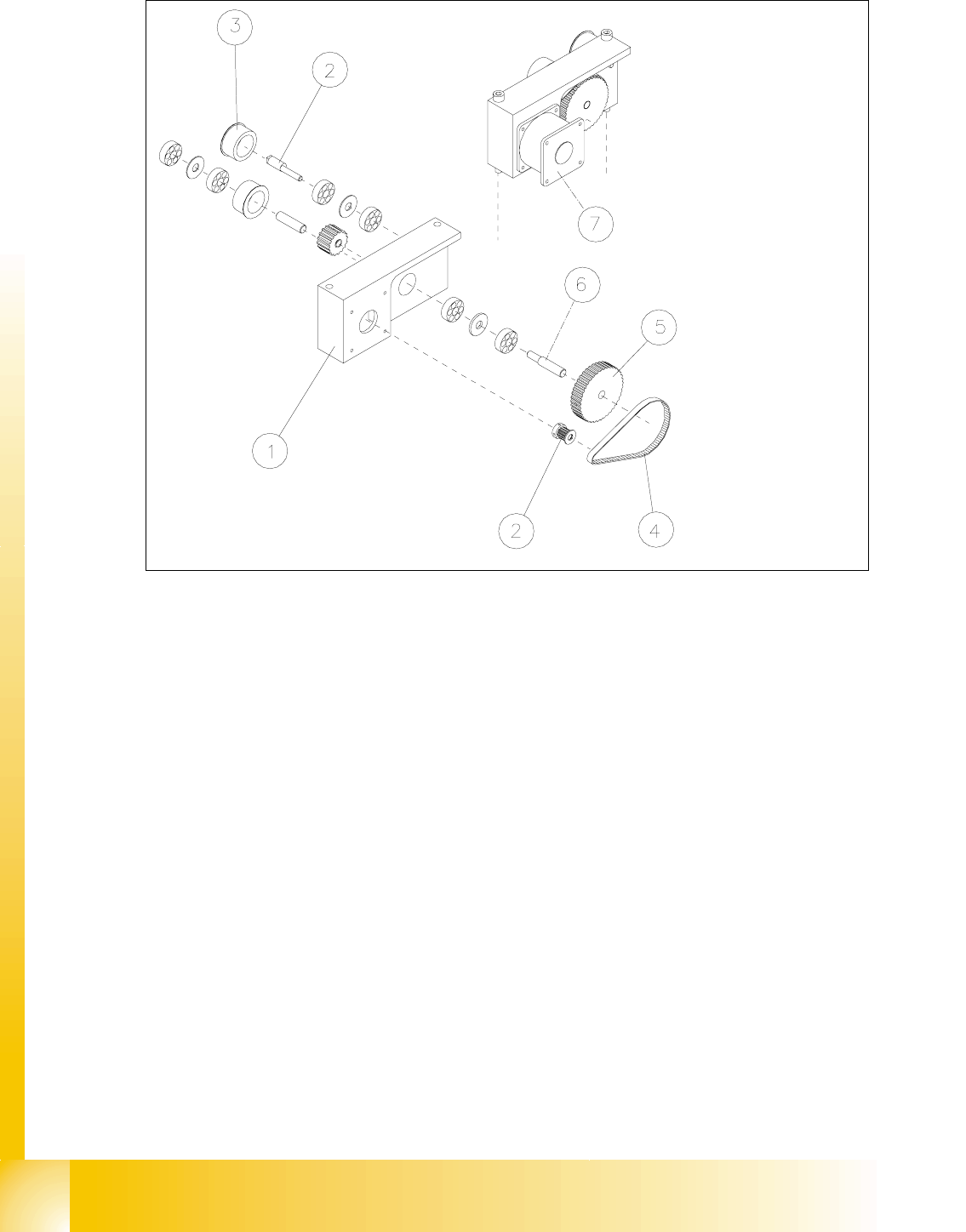
Fig. 14.3.7 Removing the Drive Unit of the Width Adjustment System: Short Toothed Belt
Removing the Toothed Belt of Width Adj. System: Loosen the Fastening of the Eccentric Axle
Key to Fig. 14.3.7
➠ Remove the lifting table as described in section 14.3.8.1.
➠ Undo the screws fastening the motor of the width adjustment system of the pertinent conveyor
1 / 2 (see Fig. 14.3.8 -> 3, 4, 5).
➠ Top the motor just slightly so that the small toothed belt comes free of the synchronizing disk
of the motor shaft (see Fig. 14.3.7 -> 4 and 2).
➠ Take the toothed belt off the drive unit.
1) Drive housing of width adj. system 2) Synchronizing disk (on motor shaft)
3) Deflection pulley for width adj. system (for
long toothed belt)
4) Eccentric axle for width adj. system
(to relieve tension on the long toothed belt)
5) Synchronizing disk for width adj. system 6) Drive shaft for width adj. system
7) Motor width adj. system, conveyor 2
(Conveyor 2 is shown)

Student Guide HS-50 Advanced II 07/2002 Edition
14 Conveyor System
41
,QVWDOOLQJD7RRWKHG%HOWIRUWKH:LGWK$GMXVWPHQW6\VWHP6KRUW
CAUTION O
The new toothed belt is not to be stretched or kinked. 14
➠ Install the new drive toothed belt in the reverse order to that described above for the removal.
Bolt the motor to the drive housing.
➠ Check: The HQWLUHZLGWKof the toothed belt must be engaged on the synchronizing disk
➠ Remove all tools, etc., from the working area of the machine.
➠ Make certain that the transmission lever on the lifting table motor mount is folded onto the lift-
ing curve (see Fig. 14.3.5, illustration bottom left).
➠ Re-install the lifting table as described in section 14.3.8.2.
➠ Carry out the appropriate )LQDOVWHSVLQFOXGLQJWKHIXQFWLRQFKHFN(see section 14.4).
During the function check, move the conveyor to its maximum and minimum width.
([FKDQJLQJWKH6WHSSLQJ0RWRURIWKH:LGWK$GMXVWPHQW6\VWHP
CAUTION O
During the following removal and installation of the motor, the toothed belt for the drive of the width
adjustment system are not to be stretched or kinked. 14
5HPRYLQJWKH6WHSSLQJ0RWRUIRUWKH:LGWK$GMXVWPHQW6\VWHP
➠ For removal, proceed as described in section 14.3.12.1.
➠ For electrical isolation, proceed as follows:
➠ Lift the cover off the relevant cable duct placed parallel to the conveyor assembly adjust-
ment plate.
➠ Carefully remove the appropriate cable ties.