HS50_advance_level 2.pdf - 第415页
Stud ent Gu ide HS-5 0 Adva nced II 07/2 002 Ed ition 14 Conve yor System 41 , QVW DOOLQJD 7 RRWKHG%HOW IRUWKH :LG W K$ GMXVWPHQW 6\ VWHP6 KRUW CA UTIO N O The new t oothed b elt is not to be stretch…

07/2002 Edition Student Guide HS-50 Advanced II
14 Conveyor System
40
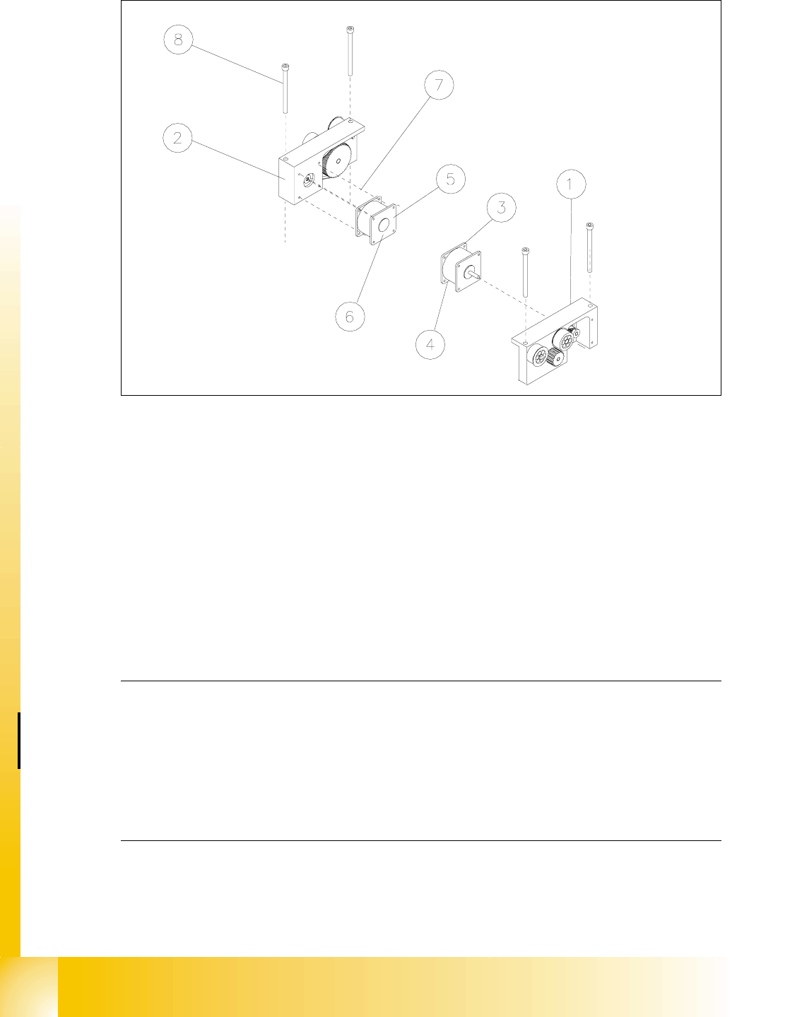
Fig. 14.3.7 Removing the Drive Unit of the Width Adjustment System: Short Toothed Belt
Removing the Toothed Belt of Width Adj. System: Loosen the Fastening of the Eccentric Axle
Key to Fig. 14.3.7
➠ Remove the lifting table as described in section 14.3.8.1.
➠ Undo the screws fastening the motor of the width adjustment system of the pertinent conveyor
1 / 2 (see Fig. 14.3.8 -> 3, 4, 5).
➠ Top the motor just slightly so that the small toothed belt comes free of the synchronizing disk
of the motor shaft (see Fig. 14.3.7 -> 4 and 2).
➠ Take the toothed belt off the drive unit.
1) Drive housing of width adj. system 2) Synchronizing disk (on motor shaft)
3) Deflection pulley for width adj. system (for
long toothed belt)
4) Eccentric axle for width adj. system
(to relieve tension on the long toothed belt)
5) Synchronizing disk for width adj. system 6) Drive shaft for width adj. system
7) Motor width adj. system, conveyor 2
(Conveyor 2 is shown)

Student Guide HS-50 Advanced II 07/2002 Edition
14 Conveyor System
41
,QVWDOOLQJD7RRWKHG%HOWIRUWKH:LGWK$GMXVWPHQW6\VWHP6KRUW
CAUTION O
The new toothed belt is not to be stretched or kinked. 14
➠ Install the new drive toothed belt in the reverse order to that described above for the removal.
Bolt the motor to the drive housing.
➠ Check: The HQWLUHZLGWKof the toothed belt must be engaged on the synchronizing disk
➠ Remove all tools, etc., from the working area of the machine.
➠ Make certain that the transmission lever on the lifting table motor mount is folded onto the lift-
ing curve (see Fig. 14.3.5, illustration bottom left).
➠ Re-install the lifting table as described in section 14.3.8.2.
➠ Carry out the appropriate )LQDOVWHSVLQFOXGLQJWKHIXQFWLRQFKHFN(see section 14.4).
During the function check, move the conveyor to its maximum and minimum width.
([FKDQJLQJWKH6WHSSLQJ0RWRURIWKH:LGWK$GMXVWPHQW6\VWHP
CAUTION O
During the following removal and installation of the motor, the toothed belt for the drive of the width
adjustment system are not to be stretched or kinked. 14
5HPRYLQJWKH6WHSSLQJ0RWRUIRUWKH:LGWK$GMXVWPHQW6\VWHP
➠ For removal, proceed as described in section 14.3.12.1.
➠ For electrical isolation, proceed as follows:
➠ Lift the cover off the relevant cable duct placed parallel to the conveyor assembly adjust-
ment plate.
➠ Carefully remove the appropriate cable ties.
07/2002 Edition Student Guide HS-50 Advanced II
14 Conveyor System
42
Fig. 14.3.8 Removing the Motor of the Width Adjustment System or the Drive of the Width Adjust. System (Complete)
Key to Fig. 14.3.8
➠ In the cable duct, disconnect the plug-and-socket connection for this motor of the width adjust-
ment system (;RU;: see circuit diagram for "6/,2PRGXOHRQ3&%FRQYH\RU
or RQ3&%FRQYH\RU.
NOTE:
If you have discovered a break in the motor cable during a continuity check and this break is up-
stream of the plug-and-socket connection, the motor cable must be run on a weaving course as
far as the "conveyor control PCB 1" / "... PCB 2" (see ) and unplugged at the connector X3 of
the corresponding "conveyor control" (see above-mentioned circuit diagram). This may be some-
what complicated due to the routing of the cable inside the machine base.
You may wish to contact Siemens SMD Service regarding this work. 14
➠ Pull the motor out of the drive housing.
1) Drive for width adj. system (complete)
(incl. Pos. 3 and 4 or 5 and 6)
2) Drive housing for width adj. system for con-
veyor 1 and 2
3) Motor width adj. system conveyor 1 4) Cable for motor width adj. system conv. 1
5) Motor width adj. system conveyor 2 6) Cable for width adj. system conveyor 2
7) Screws to fasten the motor:
4 hexagonal socket head cap screws M 3
8) 2 hexagonal socket head cap screws
M 6 x 80