HS50_advance_level 2.pdf - 第418页
07/2002 Editio n Student G uide HS -50 Advanc ed II 14 Conveyor System 44 ➠ 3ODFHWKHODUJH WRRWKHGEHO WXQGHUW HQVLRQ as descri bed in se ction 14.3.12 .2 for the i nstal- lation of the "T ooth ed belt for the w…

Student Guide HS-50 Advanced II 07/2002 Edition
14 Conveyor System
43
,QVWDOOLQJWKH6WHSSLQJ0RWRUIRUWKH:LGWK$GMXVWPHQW6\VWHP
CAUTION O
The new toothed belt is not to be stretched or kinked. 14
➠ Install the new stepping motor in the reverse order to that described above for the removal. Bolt
the motor to the drive housing.
➠ Check: The HQWLUHZLGWKof the toothed belt must be engaged on the synchronizing disk
➠ Remove all tools, etc., from the working area of the machine.
➠ Make certain that the transmission lever on the lifting table motor mount is folded onto the lift-
ing curve (see Fig. 14.3.5, illustration bottom left).
➠ Re-install the lifting table as described in section 14.3.8.2.
➠ Carry out the appropriate )LQDOVWHSVLQFOXGLQJWKHIXQFWLRQFKHFN(see section 14.4).
During the function check, move the conveyor to its maximum and minimum width.
([FKDQJLQJWKH'ULYHIRUWKH:LGWK$GMXVWPHQW6\VWHP&RPSOHWH
NOTE:
Exchange the entire unit "Drive for width adjustment system", e.g., in case of a fault in the ball
bearing/syconronizing disks and motor. 14
([FKDQJLQJWKH'ULYHIRUWKH:LGWK$GMXVWPHQW6\VWHP&RPSOHWH
➠ Remove the lifting table as described in section 14.3.8.1.
➠ Relieve the stress on the large toothed belt for the width adjustment system as described
above in section 14.3.12.1 .
Take the large toothed belt off the sprocket wheels of the drive unit.
➠ Detach the plug-and-socket connection of the motor of the width adjustment system LQWKHFD
EOHGXFWas described above in section 14.3.13.1.
➠ Undo and remove the screws fastening the drive housing to the assembly base plate (2 hex-
agonal socket head cap screws M6: see Fig. 14.3.8 -> 8). Lift the "Drive for the width adjust-
ment system" out.
,QVWDOOLQJWKH'ULYHIRUWKH:LGWK$GMXVWPHQW6\VWHP&RPSOHWH
➠ Install the new "Drive for the width adjustment system" in the reverse order to that following
during removal.
➠ Place the large toothed belt for the width adjustment system on the deflection pulleys.
➠ Check: The HQWLUHZLGWKof the toothed belt must be engaged on the two outside synchronizing
disks (on the pedestal) and must be in contact with the circumference of the deflection pulleys.

07/2002 Edition Student Guide HS-50 Advanced II
14 Conveyor System
44
➠ 3ODFHWKHODUJHWRRWKHGEHOWXQGHUWHQVLRQ as described in section 14.3.12.2 for the instal-
lation of the "Toothed belt for the width adjustment system".
➠ Remove all tools, etc., from the working area of the machine.
➠ Make certain that the transmission lever on the lifting table motor mount is folded onto the lifting
curve (see Fig. 14.3.5, illustration bottom left).
➠ Where applicable, re-install the lifting table as described in section 14.3.8.2.
➠ Carry out the pertinent )LQDOVWHSVLQFOXGLQJIXQFWLRQFKHFN(see section 14.4). During the
function check, move the conveyor to its maximum and minimum width.
([FKDQJLQJWKH/LPLW6ZLWFKHVRIWKH:LGWK$GMXVWPHQW6\VWHP
5HPRYLQJWKH/LPLW6ZLWFKHVRIWKH:LGWK$GMXVWPHQW6\VWHP
NOTE:
The limit switches are preassembled including the cables. Nevertheless, the wiring can also be
unsoldered/soldered right at the switch in question if you discover that the limit switch itself is
faulty. 14
➠ Remove the lifting table as described in section 14.3.8.1.
➠ Mark the position of the limit switch on the rail with a fine permanent marker.
➠ Unsolder the connection wires on the faulty limit switch (allocation: see circuit diagram &RQ
YH\RUFRQWURO3&% or 3&%. Comply with the NOTE below.
➠ Remove the faulty limit switch (two M2 slotted screws: see Fig. 14.3.9 -> 7 -10).
NOTE:
If you have discovered a break in the limit switch cable during a continuity check, the cable must
be run on a weaving course as far as the corresponding "Conveyor Control PCB 1" / "... 2" (al-
location: see ) and must be unplugged there at connector X12 / X13 (see above-mentioned circuit
diagram).
This may be somewhat complicated depending on the cable routing inside the machine base.
You may wish to contact Siemens SMD Service regarding this work. 14
Student Guide HS-50 Advanced II 07/2002 Edition
14 Conveyor System
45
,QVWDOOLQJWKH/LPLW6ZLWFKHVIRUWKH:LGWK$GMXVWPHQW6\VWHP
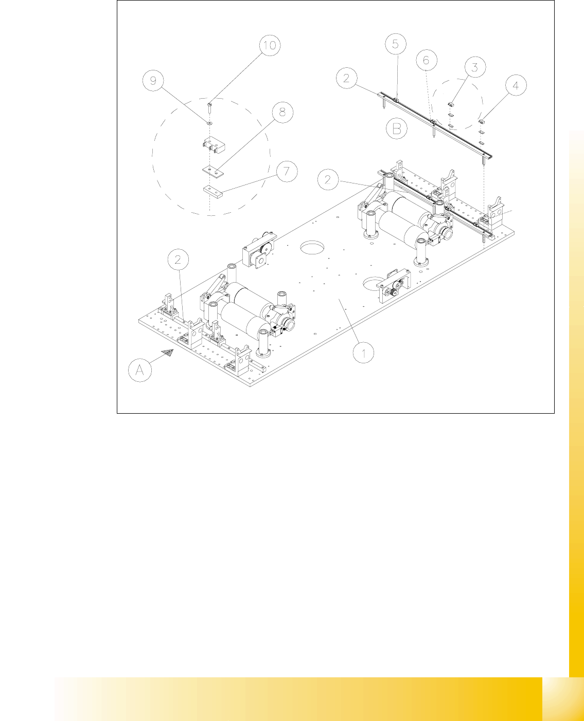
Fig. 14.3.9 Exchanging the Limit Switches for Minimum and Maximum PCB Conveyor Width
Key to Fig. 14.3.9
➠ Mount the new limit switch at the SRVLWLRQPDUNHG.
➠ Resolder the connection wires with FRUUHFWDOORFDWLRQ.
➠ Remove all tools, etc., from the working area of the machine.
A) PCB transport direction B) Set-up of limit switch
1) Mounting plate 2) Profile for limit switch
3) Limit switch maximum width (max.) con-
veyor 1
4) Limit switch minimum width (min.)
conveyor 1
5) Limit switch maximum width (max.) con-
veyor 2
6) Limit switch minimum width (min.)
conveyor 2
7) T-nut for limit switch 8) Spacer for microswitch (limit switch)
9) Disk ) 10) Slotted screw M2 x 12