HS50_advance_level 2.pdf - 第419页
Stud ent Gu ide HS-5 0 Adva nced II 07/2 002 Ed ition 14 Conve yor System 45 ,QVWDOOLQJWKH /LPLW 6ZLWFKHVIRU WKH:LGWK$ GMX VWPH QW6\ VWHP Fig. 14.3.9 Exchanging the Limit Switches f or Minimum and Maxi…

07/2002 Edition Student Guide HS-50 Advanced II
14 Conveyor System
44
➠ 3ODFHWKHODUJHWRRWKHGEHOWXQGHUWHQVLRQ as described in section 14.3.12.2 for the instal-
lation of the "Toothed belt for the width adjustment system".
➠ Remove all tools, etc., from the working area of the machine.
➠ Make certain that the transmission lever on the lifting table motor mount is folded onto the lifting
curve (see Fig. 14.3.5, illustration bottom left).
➠ Where applicable, re-install the lifting table as described in section 14.3.8.2.
➠ Carry out the pertinent )LQDOVWHSVLQFOXGLQJIXQFWLRQFKHFN(see section 14.4). During the
function check, move the conveyor to its maximum and minimum width.
([FKDQJLQJWKH/LPLW6ZLWFKHVRIWKH:LGWK$GMXVWPHQW6\VWHP
5HPRYLQJWKH/LPLW6ZLWFKHVRIWKH:LGWK$GMXVWPHQW6\VWHP
NOTE:
The limit switches are preassembled including the cables. Nevertheless, the wiring can also be
unsoldered/soldered right at the switch in question if you discover that the limit switch itself is
faulty. 14
➠ Remove the lifting table as described in section 14.3.8.1.
➠ Mark the position of the limit switch on the rail with a fine permanent marker.
➠ Unsolder the connection wires on the faulty limit switch (allocation: see circuit diagram &RQ
YH\RUFRQWURO3&% or 3&%. Comply with the NOTE below.
➠ Remove the faulty limit switch (two M2 slotted screws: see Fig. 14.3.9 -> 7 -10).
NOTE:
If you have discovered a break in the limit switch cable during a continuity check, the cable must
be run on a weaving course as far as the corresponding "Conveyor Control PCB 1" / "... 2" (al-
location: see ) and must be unplugged there at connector X12 / X13 (see above-mentioned circuit
diagram).
This may be somewhat complicated depending on the cable routing inside the machine base.
You may wish to contact Siemens SMD Service regarding this work. 14
Student Guide HS-50 Advanced II 07/2002 Edition
14 Conveyor System
45
,QVWDOOLQJWKH/LPLW6ZLWFKHVIRUWKH:LGWK$GMXVWPHQW6\VWHP
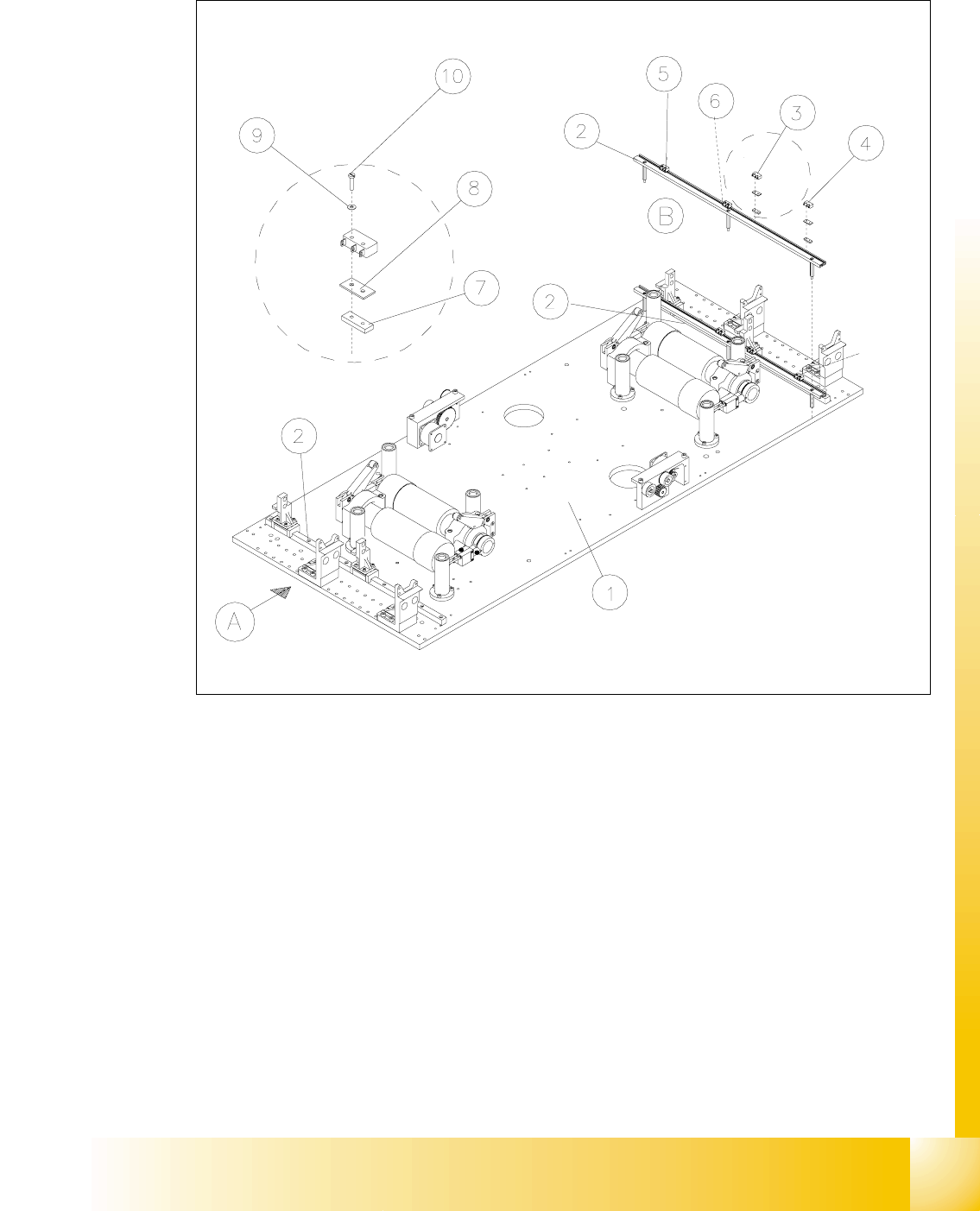
Fig. 14.3.9 Exchanging the Limit Switches for Minimum and Maximum PCB Conveyor Width
Key to Fig. 14.3.9
➠ Mount the new limit switch at the SRVLWLRQPDUNHG.
➠ Resolder the connection wires with FRUUHFWDOORFDWLRQ.
➠ Remove all tools, etc., from the working area of the machine.
A) PCB transport direction B) Set-up of limit switch
1) Mounting plate 2) Profile for limit switch
3) Limit switch maximum width (max.) con-
veyor 1
4) Limit switch minimum width (min.)
conveyor 1
5) Limit switch maximum width (max.) con-
veyor 2
6) Limit switch minimum width (min.)
conveyor 2
7) T-nut for limit switch 8) Spacer for microswitch (limit switch)
9) Disk ) 10) Slotted screw M2 x 12
07/2002 Edition Student Guide HS-50 Advanced II
14 Conveyor System
46
➠ Make certain that the WUDQVPLVVLRQOHYHU on the pertinent lifting table motor is folded down on
the lifting curve (see Fig. 14.3.5, illustration bottom left).
➠ Re-install the lifting table as described in section 14.3.8.2.
➠ Perform the pertinent )LQDOVWHSVLQFOXGLQJ)XQFWLRQ&KHFN (see section 14.4).
➠ Test the limit switch function by actuating the limit switch (manually, if applicable).
Actuating the limit switch the input signal must change from "0" -> "1".
➠ In the conveyor menu, activate the adjustment movement and - with visual inspection of
the position of the movable conveyor side relative to the limit switch - inch toward the limit
switch in small adjustment steps. When actuated, the adjusting movement must be shut
off. The associated input signals must be "1" if the limit switch is actuated.
([FKDQJLQJWKH3UR[LPLW\6ZLWFKIRUWKH3RVLWLRQRIWKH:LGWK$GMXVWPHQW
6\VWHP
For an overview of the layout of the "Proximity switch for position of the width adj. system" at con-
veyor 1 and 2 is available in . 14
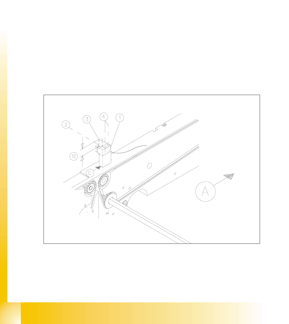
Fig. 14.3.10 Removing the Proximity Switches for the Position of the Movable Conveyor Side