HS50_advance_level 2.pdf - 第427页
Stud ent Gu ide HS-5 0 Adva nced II 07/2 002 Ed ition 14 Conve yor System 53 5HPRYL QJWKH6 WRSSHU $ VVHPEO\ Fig. 14.3.12 Rem oving the St opper Assembly Key to Fi g. 14.3.12 ➠ Removal of stop per in th e si…

07/2002 Edition Student Guide HS-50 Advanced II
14 Conveyor System
52
➠ Where applicable, push the stopper back into the correct position (centered to conveyor width).
➠ Perform the appropriate )LQDOVVWHSVLQFOXGLQJ)XQFWLRQ&KHFN(see section 14.4).
Test the stopper function in the conveyor menu (place PCB in input) or use SITEST to do so.
NOTE:
In case of a fault in the cable, the cable must be run on a weaving course as far as SLIO module
PCB1 or PCB2 (layout: see ) and plug-and-socket connection X8 or X10 on the SLIO module
PCB1 or PCB2 must be disconnected (see circuit diagram "SLIO module on PCB1" or
"...PCB2").
This may be somewhat complicated depending on the cable routes inside the machine base.
You may wish to contact Siemens SMD Service regarding this work. 14
([FKDQJLQJWKH6WRSSHU$VVHPEO\
NOTE:
Exchange the stopper assembly if the piston is sluggish or leaky.
The stoppers for all of the placement areas are of the same construction.
The assembly "Stopper assembly" is complete, including the solenoid valve (valve assembly).
The proximity switch is not included, because it is advantageous to rebuild it. 14
➠ First, proceed as follows to transfer the mounting position of the stopper to fixed side of the
conveyor:
➠ Where applicable, pull the piston of the faulty stopper out manually (position: "Stopper
moved out").
➠ Push a PCB on the piston of the stopper and transfer the leading edge of the PCB to the
fixed conveyor side with a permanent marker.
➠ Unplug the plug-and-socket connection on the solenoid valve (see Fig. 14.3.11).
➠ Loosen the clamping unit in the cover of the stopper and pull the proximity swiitch out of the
hole (see Fig. 14.3.11). Proceed further according to the conveyor at hand.
Student Guide HS-50 Advanced II 07/2002 Edition
14 Conveyor System
53
5HPRYLQJWKH6WRSSHU$VVHPEO\
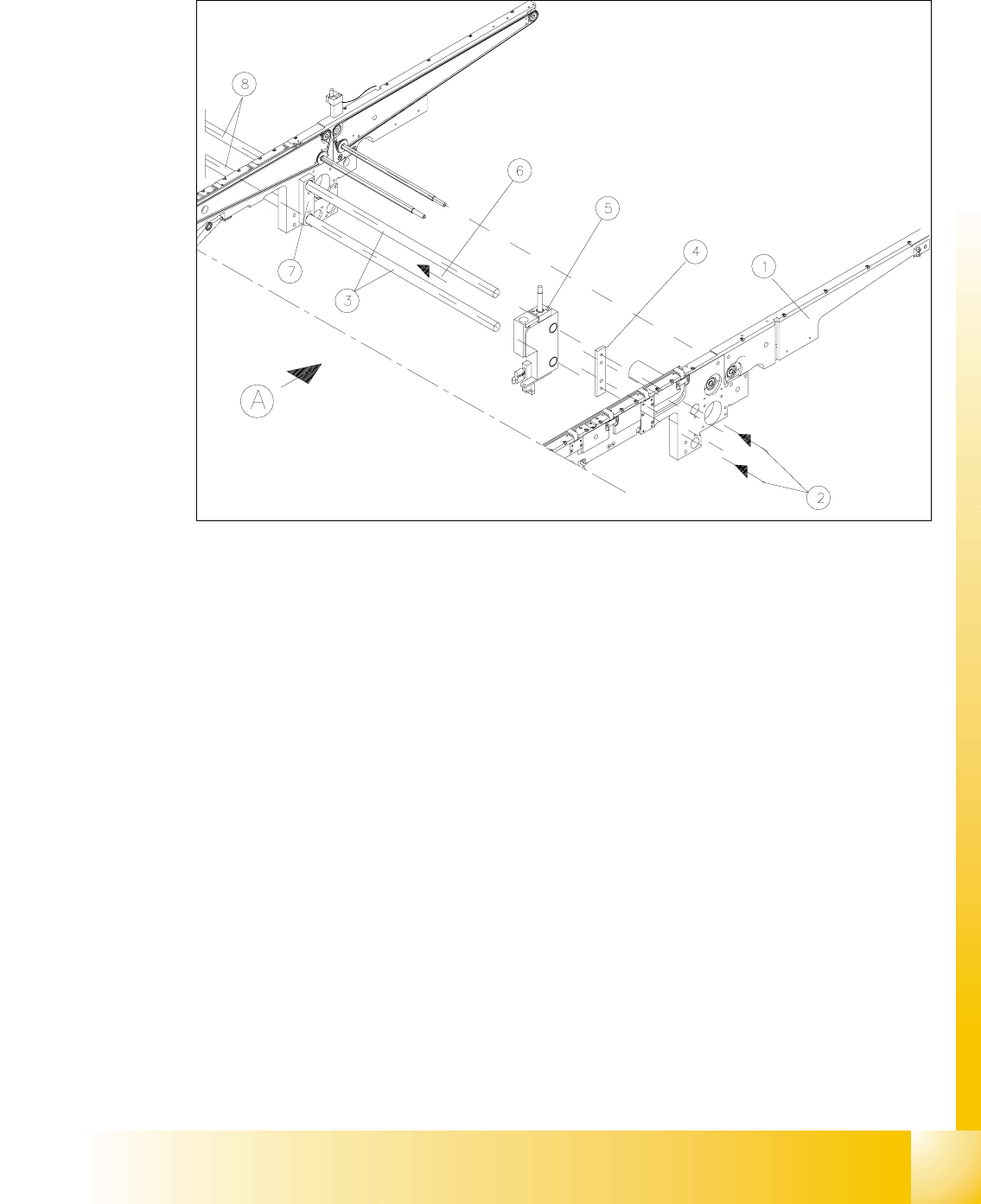
Fig. 14.3.12 Removing the Stopper Assembly
Key to Fig. 14.3.12
➠ Removal of stopper in the single conveyor:
➠ Move the conveyor to maximum width.
➠ Working from the outside of the fixed conveyor, undo the fastneing screws in the center of
the two stopper axles.The screws fastening the connecting strip on inside and outside (see
Fig. 14.3.12) are not loosened.
➠ Push the stopper axles toward the movable conveyor side until you can pull off the "Stopper
A) PCB transport direction
1) Fixed conveyor side 2) Screws fastening the stopper axles
One M6 hexagon socket head cap screw for
each
3) Stopper axles 4) Connection rail outside. If a single conveyor
is involved it is NOT REMOVED
5) Stopper assembly 6) Direction of movement: move axles
7) Connection rail inside WILL NOT BE
REMOVED
8) Continuous stopper axles on dual conveyor

07/2002 Edition Student Guide HS-50 Advanced II
14 Conveyor System
54
assembly" in the resultant fap and lift it out.
➠ Removing the stopper in conveyor 1 of the dual conveyor:
➠ Move conveyor 1 apart just far enough for the fixed side of conv. 2 to still be accessible.
➠ Working from the outside of the fixed conveyor, undo the fastening screws in the center of
the two stopper axles of conveyors 1 and 2.
➠ Push the stopper axles into conveyor 2 until you can pull off the "Stopper assembly" in the
developing gap and lift it out.
➠ Removing the stopper in conveyor 2 of the dual conveyor:
➠ Move conveyor 2 and conveyor 1 to the maximum width.
➠ To remove the stopper, proceed in an manner analogous to that used to describe the single
conveyor (see above).
➠ On the fixed conveyor side of conveyor 1, remove the "connection rail, outside" (undo 2
hexagonal socket head cap screws: see Fig. 14.3.12 -> 4).
➠ Push the stopper axles back toward conveyor and remove the stopper for conveyor 2.
,QVWDOOLQJWKH6WRSSHU$VVHPEO\
➠ Place the new "Stopper assembly" against the fixed conveyor side and push the two two stop-
per axles as far as possible into the holes in the connecting rails.
➠ Connect the plug-and-socket connection to the solenoid valve (see Fig. 14.3.11).
➠ Install the proximity switch as described in VHFWLRQ
➠ Push the stopper DJDLQVWWKHIL[HGVLGHWRDVWRS
➠ Screw down both axleseach in the center (one M6 hexagon socket head screw for each). The
fastening screws must be ORRVHQHGDJDLQODWHUWRDGMXVW the stopper.
➠ Carry out the pertinent ")LQDOVWHSV (see section 14.4).
➠ 6HWWKHVWRSSHUSRVLWLRQDVIROORZV
➠ Use the transport menu to move a PCB into the appropriate placement conveyor.
Open the safety hoods. Manually align the PCB OHDGLQJHGJHWRWKHPDUNon the fixed con-
veyor side. Hold the PCB VHFXUHO\in this position
➠ Push the stopper against the PCB until the piston which moved out is LQFRQWDFWZLWKthe
leading edge of the aligned PCB.
➠ Screw down both axles in H[DFWO\WKLVSRVLWLRQeach in the center (one M6 hexagon
socket head screw for each).
➠ Set the DFWXDWLQJGLVWDQFH of the proximity switch of the stopper as described in section
14.3.18.2.