HS50_advance_level 2.pdf - 第47页
Stud ent Gu ide HS-5 0 Adva nced II 07/2 002 Ed ition 3 Power Supply 9 6XSSO\YROW DJH V The power s upply unit is located i n the le ft-hand middl e sectio n of the p lacemen t system . A loc k- able door preve…
07/2002 Edition Student Guide HS-50 Advanced II
3 Power Supply
8
3RZHU6XSSO\XQLW
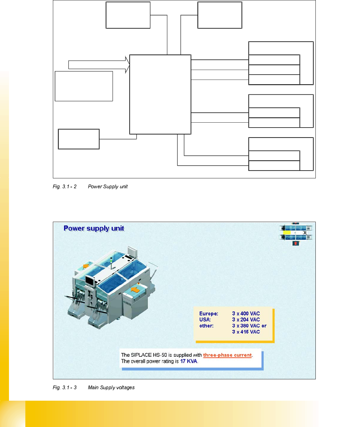
0DLQ6XSSO\YROWDJHV
Power Supply Unit
External Supply
Europe: 3 x 400V
Americas: 3 x 204V
Other: 3 x 380V or
3 x 415V
Control Unit
Servo Unit
Transport System
Component Table
Station
Computer +
Monitors
Z/DP Axes
Star Axes
X/Y Axes
Control Unit
Feeder Supply
Conveyor Motors
Lifting Tables
Service Plug

Student Guide HS-50 Advanced II 07/2002 Edition
3 Power Supply
9
6XSSO\YROWDJHV
The power supply unit is located in the left-hand middle section of the placement system. A lock-
able door prevents access to the unit.
The power supply unit provides the following supply voltages:
– 200 VDC for the servo amplifiers of the x and y axes
– 100 VDC/4 VDC for the servo amplifiers of the star
– 30 VDC for the servo amplifiers the z and dp axes
– 52 VDC for the DC/DC converters in the control unit
– 40 VDC for the component tables and the PCB handling system
– 10 VDC for the component tables
– 3 x 230 VAC for the lifting table motors of the single or dual conveyor (option)
– 230 VAC for the UPS for the station computer and monitors
For the service socket
PLEASE NOTE: The service socket can only be used if the placement system is con-
nected to the main power supply with a 5-conductor cable (L1, L2, L3, N, PE).
9ROWDJHVLQWKHSRZHUVXSSO\XQLWDIWHUVZLWFKLQJRQDWWKHPDLQVZLWFK
When the main switch is switched on, the following voltages are generated and may or may not
be switched through to the modules:
230 VAC (Europe) Input 3 x 400 VAC
115 VAC (U. S. A.) Input 3 x 204 VAC
130 VAC (other) Input 3 x 230 VAC
220 VAC (other) Input 3 x 380 VAC
240 VAC (other) Input 3 x 415 VAC
Voltage Module
200 VDC Servo unit Not enabled
100 VDC Servo unit Not enabled
4 VDC Servo unit Enabled
30 VDC Servo unit Enabled
52 VDC Control unit Enabled
40 VDC Component tables, PCB handling system Enabled
10 VDC Component table Enabled
3 x 230 VAC Lifting table motors Not enabled
230 VAC Station computer and PC Enabled
230 or 115 or 240 VAC Service socket Independent of the main switch

07/2002 Edition Student Guide HS-50 Advanced II
3 Power Supply
10
&RQWUROXQLW
When the main switch is switched on, the DC/DC converters in the control unit are supplied with
52 VDC by the power supply unit. The following voltages are then generated in the control unit:
+ 5 VDC to supply the digital electronic circuits
± 12 VDC to supply the digital electronic circuits
± 15 VDC to supply the analogue electronic circuits
+ 24 VDC to supply the control circuits, relays, etc.
The measuring points are shown in the block diagram "HS-50 control unit, front view, 00334808-
XXXXXXTD3" in chapter 3 of the detailed circuit diagrams.
0DLQGLVWULEXWLRQXQLW
Once the placement system has been switched on, the following voltages can be tapped at the
terminal strip for the main distribution unit (see block diagram "Main distribution unit, 00336154-
XXXXXXTD3 in chapter 3" of the detailed circuit diagrams):
6WDELOL]HGYROWDJHV
5 VDC, ± 12 VDC, ± 15 VDC, 24 VDC
1RQVWDELOL]HGYROWDJHV
10 VDC, 40 VDC, 52 VDC
6HUYRXQLW
When the main switch is switched on, the servo unit is supplied with the following voltages:
The test sockets are shown in the block diagram "HS-50 servo unit, front view, 00334810-
XXXXXXTD3, page 1" of the detailed circuit diagrams.
The ± 15 VDC supply voltages for the servo unit’s electronic circuits are generated from the ± 15 V
supply integrated in the servo unit and can be tapped at the measuring points of the power supply
unit (see HS-50 servo unit, front view, 00334810-XXXXXXTD3, page 2 of the detailed circuit dia-
grams).
0HDVXULQJSRLQW 0HDVXUHGDJDLQVW;9
X4 0 VDC for the servo amplifiers of the x/y axes
X3 4 VDC for the servo amplifiers of the star axis
X2 30 VDC for the servo amplifiers of the z and dp axes