HS50_advance_level 2.pdf - 第52页
07/2002 Editio n Student G uide HS -50 Advanc ed II 3 Power Sup ply 14 0RGXOH 'HVLJQDWLRQ 7 HUPLQDOV 9 ROWD JHV X1 Term inal pan el Power supply U, V, W 3 x 204 VAC / 3 x 230 VAC / 3 x 380 VAC 3 x 400 VAC / 3 x 415 …
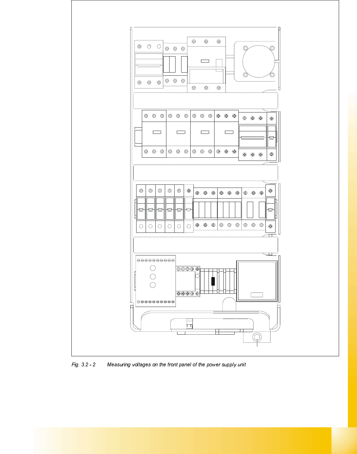
Student Guide HS-50 Advanced II 07/2002 Edition
3 Power Supply
13
246
135
F3
135
246
SZ1
K14
K12
K11
135
246
MS1A
MS1
S1
MS5 MS6MS4MS3
135
2 64 2 64
1 53 31 5
42 6 624
513
F4
426
31 5
F10F9F8F7F6F5
111111
222 222
F1
2
1
SZ2 SZ3
SZ23
246
135135
2462
4
6
1 3
5
K232
K234
K34
K33
K32
K31
K21
K22
K23
K24
SSK
1 375
4268
A1+
A2-
SZ4
X1
VUWW
PE
PE
N
BU1
M8
F11
2
1
54 6614 24 4434X4 X6L-
13L+ X3X1 X5 533323 43 65
Netz
Power
Channel 1
Kanal 1
Channel 2
Kanal 2

07/2002 Edition Student Guide HS-50 Advanced II
3 Power Supply
14
0RGXOH 'HVLJQDWLRQ 7HUPLQDOV 9ROWDJHV
X1
Terminal panel
Power supply
U, V, W
3 x 204 VAC / 3 x 230 VAC / 3 x 380 VAC
3 x 400 VAC / 3 x 415 VAC
BU1 Service socket 115 / 130 / 220 / 230 / 240 VAC
S1
Main switch
1, 3, 5 and
2, 4, 6
3 x 204 VAC / 3 x 230 VAC / 3 x 380 VAC
3 x 400 VAC / 3 x 415 VAC
MS1
Motor circuit-breaker
1, 3, 5 and
2, 4, 6
3 x 204 VAC / 3 x 230 VAC / 3 x 380 VAC
3 x 400 VAC / 3 x 415 VAC
SZ1
Main contactor
1, 3, 5 and
2, 4, 6
3 x 204 VAC / 3 x 230 VAC / 3 x 380 VAC
3 x 400 VAC / 3 x 415 VAC
MS3
MS4
MS5
MS6
Motor circuit-breaker
PCB conveyor 1
Motor circuit-breaker
PCB conveyor 2 (option)
1, 3, 5 and
2, 4, 6
1, 3, 5 and
2, 4, 6
3 x 230 VAC
3 x 230 VAC
3 x 230 VAC
3 x 230 VAC
SZ2
Contactor
1, 3, 5
2, 4, 6
3 x 140 VAC
3 x 140 VAC
SZ3
Contactor
1, 3, 5
2, 4, 6
3 x 140 VAC
3 x 140 VAC
SZ23
Contactor
1, 3, 5
2, 4, 6
3 x 140 VAC
3 x 140 VAC
SZ4 Contactor A1 (+) - A2 (-) 24 VDC
1, 2 24 VDC against ground
3, 4 24 VDC against ground
5, 6 24 VDC against ground
SSK
Combined contactor/
protective device L+, X3, X5 24 VDC against ground
F1 Fuse 1, 2 115 VAC / 130 VAC / 220 VAC
230 VAC / 240 VAC
against N on terminal panel X1
F3 Fuse 1, 3, 5 3 x 230 VAC
2, 4, 6
F4 Fuse 1, 3, 5 3 x 140 VAC
2, 4, 6
F5 Fuse 1, 2 100 VDC against negative pole of
rectifier V3 (see Fig. 3.2 - 3
on page 3 - 16)
F6 Fuse 1, 2 30 VDC against negative pole of rectifier
V4 (see Fig. 3.2 - 3
on page 3 - 16)
F7 Fuse 1, 2 40 VDC against negative pole of rectifier
V5 (see Fig. 3.2 - 3
on page 3 - 16)
F8 Fuse 1, 2 40 VDC against negative pole of rectifier
V5 (see Fig. 3.2 - 3
on page 3 - 16)
F9 Fuse 1, 2
10 VDC against negative pole of rectifier
V6
(see Fig. 3.2 - 3
on page 3 - 16)
F10 Fuse 1, 2 52 VDC against negative pole of rectifier
V7 (see Fig. 3.2 - 3
on page 3 - 16)
F11 Fuse 1, 2 30 VDC against negative pole of rectifier
V8 (see Fig. 3.2 - 3
on page 3 - 16)

Student Guide HS-50 Advanced II 07/2002 Edition
3 Power Supply
15
0HDVXULQJYROWDJHVDWUHFWLILHUV9WR9
The following diagram shows the position of rectifiers V1 to V8 and their terminal assignments.
To take measurements on rectifiers V1 and V7, you must first remove the perspex safety panel.
RISK OF DEATH BY ELECTRIC SHOCK
➠ Switch the placement system off at the main switch.
➠ Disconnect the placement system from the power supply.
➠ Wait approximately 1 minute until the residual voltages have dropped to a safe level (electro-
lytic capacitor C1).
➠ Loosen the two M5 fillister head screws on rectifiers V1 and V7.
➠ Remove the perspex safety panel.
➠ Switch the placement system on and start it up.
➠ Measure the voltages.
PLEASE NOTE:
The placement system must have started, otherwise there will be no AC voltage (3 x 140 VAC) at
rectifier V1. V1 uses the 3 x 140 VAC to generate the 200 VDC supply voltage for the servo am-
plifiers of the gantry axes and 100 VDC for the servo amplifiers of the star axes. These 100 VDC
and 4 VDC supplies are fed to the AC voltage inputs of rectifier V2. Rectifier V2 serves to "OR"
the 4 VDC and 100 VDC supplies. If the placement system has not started, only 4 VDC will be
present at the positive pole of rectifier V2.