HS50_advance_level 2.pdf - 第60页
07/2002 Editio n Student G uide HS -50 Advanc ed II 3 Power Sup ply 22 6DIHW \ FLUFXLW 6 WUXFWX UHRIWKH VDIHW\FLUFXLW The foll owing con tacts are connect ed in s eries and form t he safety circu it l…
Student Guide HS-50 Advanced II 07/2002 Edition
3 Power Supply
21
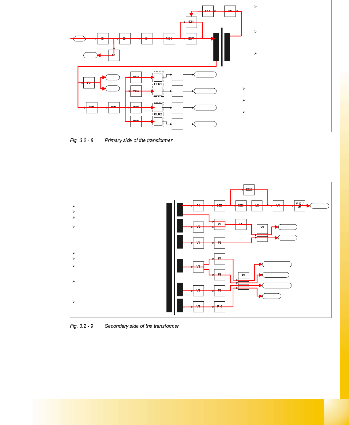
3ULPDU\VLGHRIWKHWUDQVIRUPHU
6HFRQGDU\VLGHRIWKHWUDQVIRUPHU
Bu1
St1
PC
Monitor
Lifting table 1
Lifting table 2
Lifting table 3
Lifting table 4
X5
X8
X7
X6
With the machine switched on by the
main switch (Z1), power ist first supplied
over the inrush current limiter (EST) to
the primary side of the transformer
This causes a small feedback signal on
the secondary side, which activates
contactor SZ1.
With contactor SZ1 activated the inrush
current limiter (EST) is short circuit and
furthermore without function. The
machine is now ready for operation.
On the primary side can be found the power
supply for the service plug (Bu1),
the board net where the station computer and
the two monitor are connected to
and the power supply of the four lifting tavle
motor.
X/Y axes
Star axes
Z/DP axes
Component table 1
Conveyor system
Component table 2
Control unit
W
ith the primary side connected to the main
s
upply voltage bypassing the inrush current
l
imiter the secondary side drives now also:
Supply voltage for the control unit
Supply voltage for the component table logic
Supply voltage for the component table to
drive the feeder modules
The SSK activates then contactor SZ2 and SZ3
by a 24V signal and voltage is supplied over
the inrush current limiter (ILS) to X and Y.
With a short delay also contactor SZ23 is
activated by the 24V to short circuit contactor
SZ3 as well as the inrush current limiter (ILS).
X and Y are now driven by full power.
F
or all the other voltages first the machine
h
as to be started by the
ON button
.
Reduced supply voltage for the Star-axis
With X and Y fully suplied also the Star axis is
now supplied by the main voltage.
Supply voltage to be conveyor motors
Supply voltage for the Z/DP-axis

07/2002 Edition Student Guide HS-50 Advanced II
3 Power Supply
22
6DIHW\FLUFXLW
6WUXFWXUHRIWKHVDIHW\FLUFXLW
The following contacts are connected in series and form the safety circuit loop:
– make contacts for the four protective cover switches
– make contacts for the two PCB conveyor covers
– make contacts for the two emergency stop mushroom-head push-buttons
– make contacts for the four component tables
– make contacts for the four flaps over the push-buttons for raising and lowering the component
tables
– channels 2 and 3 of the protective contactor combination (PCC)
If the safety loop is closed, 24 VDC is present at channels 2 and 3 of the PCC. The two green
LEDs for channels 2 and 3 light up in addition to the green power ON LED.
6WUXFWXUHRIWKHVLJQDOOLQJFLUFXLW
The six signalling contacts for the covers are connected in parallel and form the "Cover signal"
circuit. If one or more covers are opened, the contacts close - the 24 V signal reaches the CAN
bus and signals that one of the covers is open.
The two signalling contacts for the emergency stop mushroom-head push-button are connected
in parallel and form the "Emergency stop mushroom-head push-button signal" circuit. When an
emergency stop mushroom-head push-button is pressed, a 24 V signal is sent to the CAN bus
and signals that one of the emergency stop mushroom-head push-buttons has been pressed.
The four signalling contacts for the push-button flaps are connected in parallel. They form the
"Flaps signal" circuit. If one or more flaps is raised, a 24 V signal is applied to the CAN bus and
signals that one of the cover flaps is not closed.
The four signalling contacts for the component tables are connected in series and form the "Com-
ponent table signal" loop. If a component table is missing, a 0 V signal is sent to the CAN bus. If
all the tables are connected, the signal is approximately 16 V.
)XQFWLRQDOGHVFULSWLRQRIWKHVDIHW\FLUFXLW
The following conditions must be fulfilled before the placement system can be started or oper-
ated:
– all four component changeover tables must be docked and connected.
– all covers - four over the gantries, one over the PCB input belt and one over the output belt -
must be closed.
– both emergency stop mushroom-head push-buttons must be released

Student Guide HS-50 Advanced II 07/2002 Edition
3 Power Supply
23
– all four flaps over the push-buttons for raising and lowering the component changeover tables
must be closed.
– the minimum operating pressure must have been reached.
– the software enable must have been given, thus activating the safety circuit.
– the power supply must be sending 24 V to the Start buttons and the protective contactor com-
bination.
– If one of the Start buttons is now pressed, the protective contactor combination (PCC) will
switch and activate the following components:
– 200 V link voltage for the servo amplifier for the gantry axes
– 100 V link voltage for the star axes
– 230 V operating voltage for the lifting table motors
– the servo unit will receive a "Servo enable" signal for the servo amplifier
– 34 V operating voltage is switched to the component changeover tables
– 24 V operating voltage is switched to the used tape cutters.
The machine is now ready for service.