HS50_advance_level 2.pdf - 第64页
07/2002 Editio n Student G uide HS -50 Advanc ed II 3 Power Sup ply 26 66.D QGVRI WZ DUH UHOHDVH The placem ent syste m cann ot be used i n placem ent mode until all the s uppl y voltages ha ve been enabled by t…
Student Guide HS-50 Advanced II 07/2002 Edition
3 Power Supply
25
+24V
pressur sensor
E-stops
protective covers
component table
component flaps
SZ4
X3 (Input)
X4 (Input)
X7 (Input)
X8 (Input) X16 (Input)
X1 (Input)
X5 (Input)
X9 (Input)
X2 (Output)
+24V
Key
left side
Key
right side
Key
Key
Output
Conveyor
Start
Stop
Start
Stop
Start
Stop
Start
Stop
Key
Key
Intput
Conveyor
Start
Stop
Start
Stop
L+ X1 X3 X5
L- X2 X4 X6
X11 (Input)
+24V
SSK
Ctrl _ON
SZ4SZ3SZ2SZ1SZ23
Ready
GND
SZ23
Contro l_ON
X14
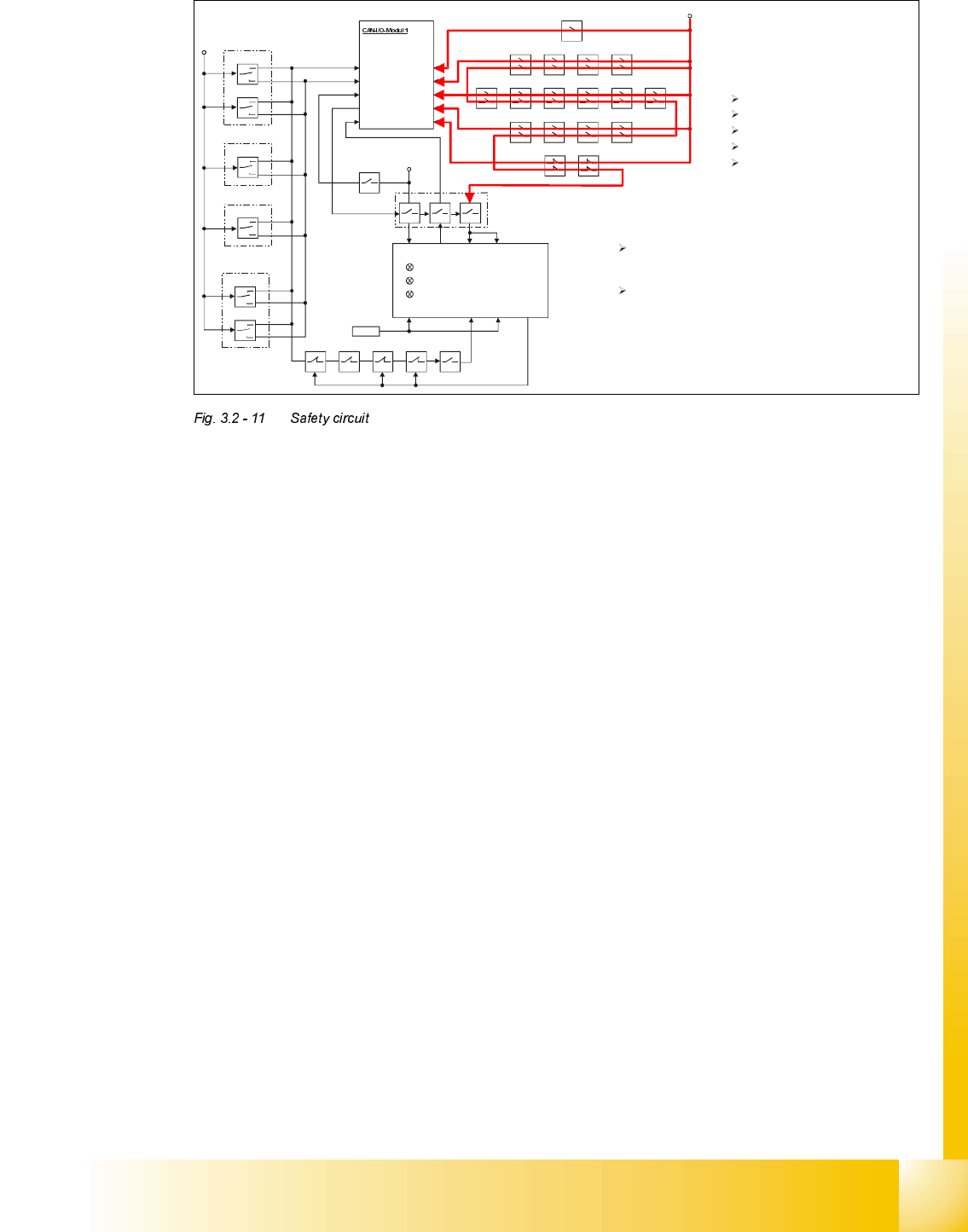
To be able to start the machine the
safety loop must be closed . The safety
loop consists of:
E-Stops
Component flaps
protective covers
component tables
pressure sensor
With the safety loop closed two functions are fullfilled :
Via the SLIO-module 1
and the
CAN-Bus all devices
are recognized and no error message is sent from the
machine controller to the station computer.
24V are also connected to the SSK giving the
permission to activate the machine software .
07/2002 Edition Student Guide HS-50 Advanced II
3 Power Supply
26
66.DQGVRIWZDUHUHOHDVH
The placement system cannot be used in placement mode until all the supply voltages have been
enabled by the protective circuit. The following conditions must also be fulfilled:
– All four component change-over tables must be docked.
– All covers must be closed.
– Both emergency stop push-buttons must be released.
– All four component flaps over the component tables must be closed.
– The software enable signal must have been sent.
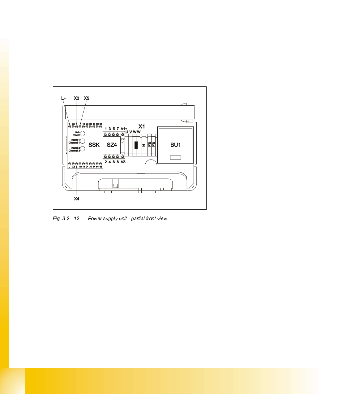
The enable signal is then sent to contactor SZ4 in the power supply unit via port 2 (X2dm) of CAN
input/output module 1 in sector 4 of the distribution board (see block diagram "Distribution board,
sector 4, 00336153-XXXXXXTD3 in the detailed circuit diagrams).
Contactor SZ4 switches 24 VDC to
– L+ on the combined contactor/protective device SSK
– the Start button at X4 of the SSK and
– the emergency stop loop at X3 and X5 on the SSK.
If 24 V is present at L+ on the SSK, the green "Power" LED on the SSK will light up. The message
"M ready" is returned to the computer via port 1 (X1dm) of the CAN input/output module 1 in sector
4 of the distribution board. If the safety loop is closed (covers closed, emergency stop button not
pressed), 24 V is sent to terminals X3 and X5 on the SSK.
If one of the Start buttons is pressed, the SSK switches and the green LEDs for channel 1 and
channel 2 light up. The five normally open contacts on the SSK switch five independent circuits
(see HS-50 power supply, 00336145-010101LD4, in the detailed circuit diagrams):
Student Guide HS-50 Advanced II 07/2002 Edition
3 Power Supply
27
– Normally open contact 13-14 actuates SZ2, SZ3 and SZ 23.
SZ2 and SZ3 switch through the 200 VDC and 100 VDC link circuit voltages for the servo
amplifiers of the x, y and star axes. SZ23 switches the current limitation.
– Electronic load disconnecting relay ELR1 switches the 3 x 230 VAC operating voltage for
lifting tables 1 and 2 of conveyor 1,
– The optional relay ELR2 switches through the voltage for lifting tables 3 and 4 of conveyor 2.
– An auxiliary contact on contactor SZ23 sends a 24 V signal in the form of an "M_controller
ON" message to CAN input/output module 1 (X1dm) and in the form of a "ServoEnable"
message to the servo unit.
– Normally open contact 23-24 switches the 40 VDC operating voltage to the component ta-
bles.
– Normally open contact 33-34 switches through the 24 VDC operating voltage to the used
tape cutter.
– Normally open contacts 43-44 and 53-54 are provided for the safety loops of external mod-
ules.
+24V
pressur sensor
E-stops
protective covers
component table
component flaps
SZ4
X3 (Input)
X4 (Input)
X7 (Input)
X8 (Input) X16 (Input)
X1 (Input)
X5 (Input)
X9 (Input)
X2 (Output)
+
24V
Key
left side
Key
right side
Key
Key
Output
Conveyor
Start
Stop
Start
Stop
Start
Stop
Start
Stop
Key
Key
Intput
Conveyor
Start
Stop
Start
Stop
L+ X1 X3 X5
L- X2 X4 X6
X11 (Input)
+24V
SSK
Ctrl _ON
SZ4SZ3SZ2SZ1SZ23
Ready
GND
SZ23
Control_ON
X14
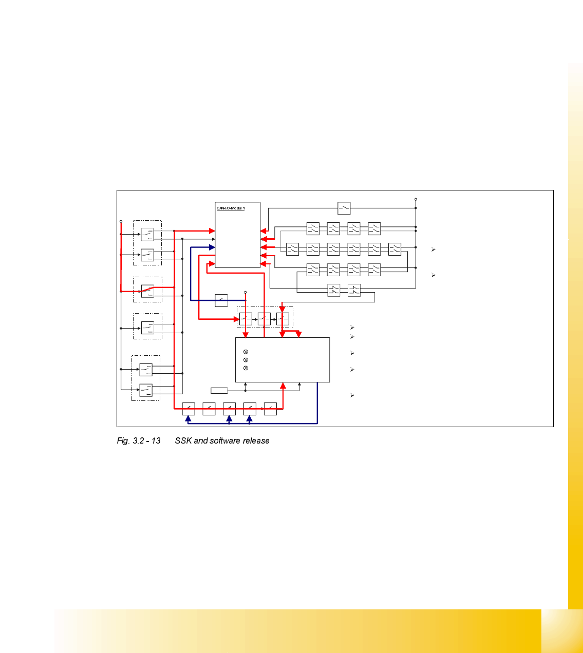
Pressing one of the START keys
connects +24V to SLIO-Port X7 and to
the still open contact on contactor SZ4
With the safety circuit closed the machine
is
ready to be activated by the START key.
Recognising the START- Key being
pressed the machine controller sets
via the CAN-Bus the Ctrl_ON signal
on port X2 energizing contactor SZ4.
SZ4 energized the following will happen:
L+ gets 24V connected to, contactor k1 of the SSK (internal)
latches and the first green LED lights up.
Internally connected to L+, X1 feeds back the READY signal to
the machine controller via port X1 of the SLIO module 1.
+24V from safety loop are connected to X3 and X5 of the SSK
With +24V now also on X4 of the SSK k2 and k3 (internal)
latches and output X14 drives +24V energizing SZ2, SZ3
and by a small delay SZ23.
With SZ2, SZ3 and SZ23 energized the +24V on input X4 is
pulled back and the Control _ON signal (+24V) is set, indicating
the main contactor is closed . The machine is now ready for
reference.