HS50_advance_level 2.pdf - 第66页
07/2002 Editio n Student G uide HS -50 Advanc ed II 3 Power Sup ply 28 5HSOD FLQJS DU W V 6DIHW\LQVWUXFWLRQV DANGER The plac ement sys tem is supp lied with 3 x 4 00 V AC (or 3 x 204 V AC / 3 x 230 V AC / 3 x…
Student Guide HS-50 Advanced II 07/2002 Edition
3 Power Supply
27
– Normally open contact 13-14 actuates SZ2, SZ3 and SZ 23.
SZ2 and SZ3 switch through the 200 VDC and 100 VDC link circuit voltages for the servo
amplifiers of the x, y and star axes. SZ23 switches the current limitation.
– Electronic load disconnecting relay ELR1 switches the 3 x 230 VAC operating voltage for
lifting tables 1 and 2 of conveyor 1,
– The optional relay ELR2 switches through the voltage for lifting tables 3 and 4 of conveyor 2.
– An auxiliary contact on contactor SZ23 sends a 24 V signal in the form of an "M_controller
ON" message to CAN input/output module 1 (X1dm) and in the form of a "ServoEnable"
message to the servo unit.
– Normally open contact 23-24 switches the 40 VDC operating voltage to the component ta-
bles.
– Normally open contact 33-34 switches through the 24 VDC operating voltage to the used
tape cutter.
– Normally open contacts 43-44 and 53-54 are provided for the safety loops of external mod-
ules.
+24V
pressur sensor
E-stops
protective covers
component table
component flaps
SZ4
X3 (Input)
X4 (Input)
X7 (Input)
X8 (Input) X16 (Input)
X1 (Input)
X5 (Input)
X9 (Input)
X2 (Output)
+
24V
Key
left side
Key
right side
Key
Key
Output
Conveyor
Start
Stop
Start
Stop
Start
Stop
Start
Stop
Key
Key
Intput
Conveyor
Start
Stop
Start
Stop
L+ X1 X3 X5
L- X2 X4 X6
X11 (Input)
+24V
SSK
Ctrl _ON
SZ4SZ3SZ2SZ1SZ23
Ready
GND
SZ23
Control_ON
X14
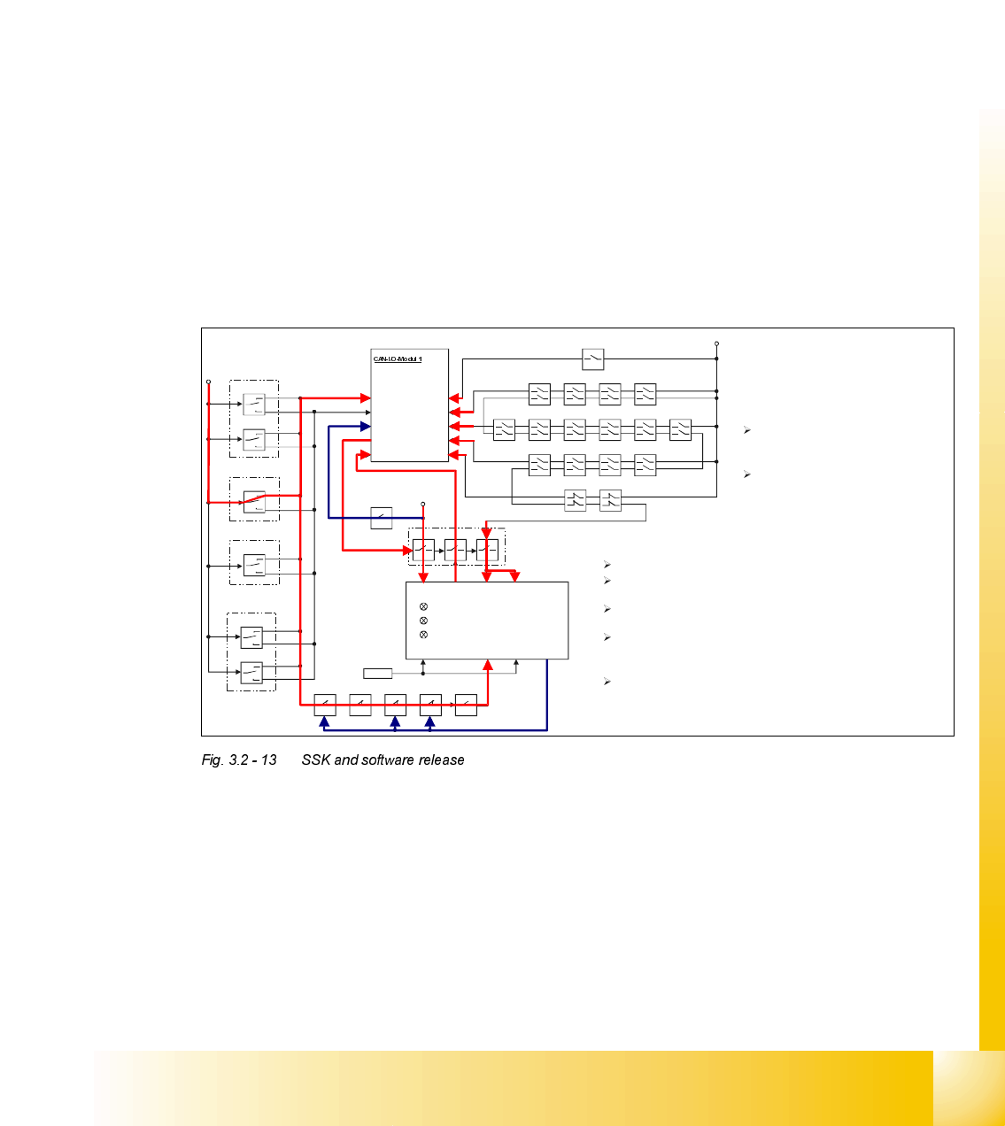
Pressing one of the START keys
connects +24V to SLIO-Port X7 and to
the still open contact on contactor SZ4
With the safety circuit closed the machine
is
ready to be activated by the START key.
Recognising the START- Key being
pressed the machine controller sets
via the CAN-Bus the Ctrl_ON signal
on port X2 energizing contactor SZ4.
SZ4 energized the following will happen:
L+ gets 24V connected to, contactor k1 of the SSK (internal)
latches and the first green LED lights up.
Internally connected to L+, X1 feeds back the READY signal to
the machine controller via port X1 of the SLIO module 1.
+24V from safety loop are connected to X3 and X5 of the SSK
With +24V now also on X4 of the SSK k2 and k3 (internal)
latches and output X14 drives +24V energizing SZ2, SZ3
and by a small delay SZ23.
With SZ2, SZ3 and SZ23 energized the +24V on input X4 is
pulled back and the Control _ON signal (+24V) is set, indicating
the main contactor is closed . The machine is now ready for
reference.

07/2002 Edition Student Guide HS-50 Advanced II
3 Power Supply
28
5HSODFLQJSDUWV
6DIHW\LQVWUXFWLRQV
DANGER The placement system is supplied with 3 x 400 VAC (or 3 x 204
VAC / 3 x 230 VAC / 3 x 380 VAC / 3 x 415 VAC) ± 5 %, 50/60 Hz main power voltage.
– Consequently, parts of the system carry potentially lethal voltages, even when switched off at
the main switch.
– Incorrect handling of the placement system can therefore result in death or severe injury or
considerable damage to equipment.
– Measurements and repairs must always be carried out by appropriately qualified personnel.
– Always follow the safety instructions in section 2 of this manual.
– Always follow the applicable accident prevention and VDE regulations (particularly DIN EN 60
204 part 1) or the regulations specific to your country.
– Before starting any repairs, switch off at the main switch and disconnect the placement system
from the main power supply.
– Secure the system to prevent it being switched on again. If these instructions are not followed,
it is possible to touch live parts, which could result in death or severe injury.
3UHSDULQJWKHSRZHUVXSSO\XQLWIRUUHSODFLQJSDUWV
➠
End all placement operations on the placement system.
➠ Shut down the Windows NT operating system correctly, otherwise problems may occur when
restarting or data may be lost.
➠ Switch the placement system off at the main switch.
➠ Disconnect the placement system from the main power supply.
➠ Secure the placement system to prevent it being switched on again and put up a sign to indi-
cate that servicing work is being carried out (see section 2, Operational safety).
➠ Open the safety doors with the double-bit key.
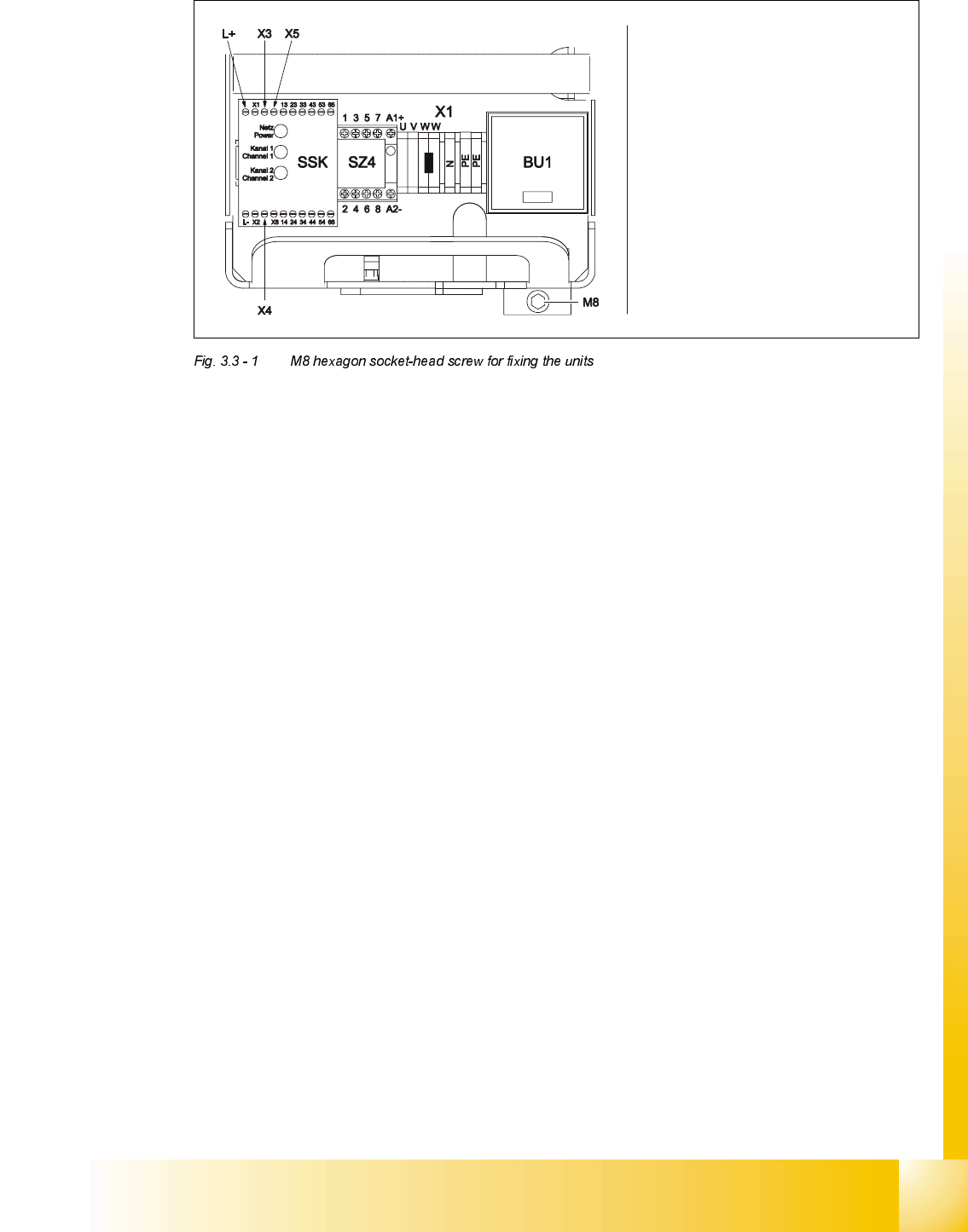
➠ Loosen the M8 hexagon socket-head screw fixing the unit to the underside of the front panel
(see Fig. 3.3 - 1
on page 3 - 29).
Student Guide HS-50 Advanced II 07/2002 Edition
3 Power Supply
29
:KDWWRGRRQFRPSOHWLRQRIWKHVHUYLFLQJZRUN
➠ Fit the power supply unit and fix in place with the M8 hexagon socket-head screw
➠ Make sure that you do not squash the cable when inserting the board
➠ Lock the safety doors
➠ Remove the key and keep in a safe place
5HSODFLQJWKHPDLQVZLWFK6
7RROVDQGHTXLSPHQW
– Set of slotted-head screwdrivers
– Set of DIN 911 Allen keys
– Digital multimeter
– Self-adhesive labels
– HS-50 detailed circuit diagrams
3DUWV
32C4/3-pole/40A main switch, item number 00342395-01
Carefully remove the unit
Make sure that the cable does
not get caught up
Be careful not to damage the
insulation