HS50_advance_level 2.pdf - 第75页
Stud ent Gu ide HS-5 0 Adva nced II 07/2 002 Ed ition 3 Power Supply 37 ➠ Connect u p the term inal wir es. ➠ Insert t he motor tri p block (see sec tion 3.3.5.4 on page 3 - 33 ). ➠ Use the di gital voltm eter t o measur…
07/2002 Edition Student Guide HS-50 Advanced II
3 Power Supply
36
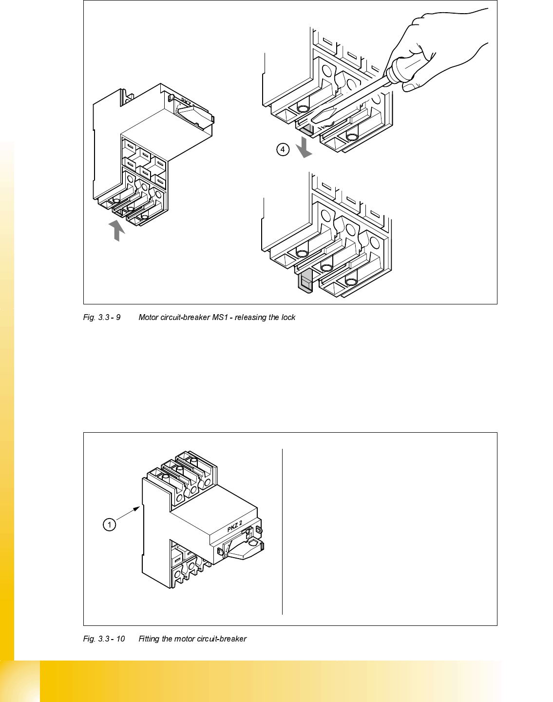
➠ Use the screwdriver to press down the locking lug (4) on the back of the motor circuit-breaker.
➠ Tilt the motor circuit-breaker upwards and pull forward to remove.
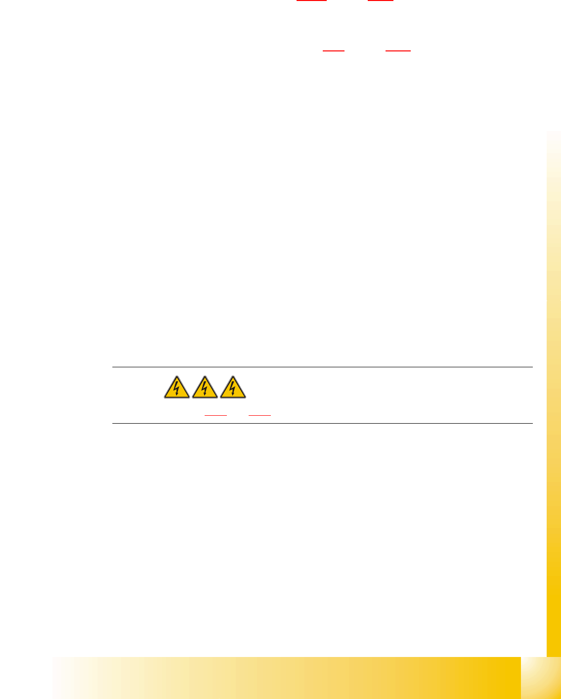
)LWWLQJPRWRUFLUFXLWEUHDNHU06
Attach the motor circuit breaker
at position 1 on the top hat rail
Push down lightly on the motor circuit-
breaker until it snaps into place
Check that the motor circuit-breaker
is seated firmly
Student Guide HS-50 Advanced II 07/2002 Edition
3 Power Supply
37
➠ Connect up the terminal wires.
➠ Insert the motor trip block (see section 3.3.5.4 on page 3 - 33).
➠ Use the digital voltmeter to measure the supply voltages at terminals L1, L2, L3 or T1, T2 and
T3.
➠ Complete the servicing work as described in 3.3.3 on page 3 - 29.
5HSODFLQJFRQWDFWRU6=
7RROVDQGHTXLSPHQW
– Set of slotted-head screwdrivers
– Self-adhesive labels
– Digital multimeter
– HS-50 detailed circuit diagrams
3DUWV
SIRIUS 3RT10/24 VDC contactor, size S2, item number 00341201-01
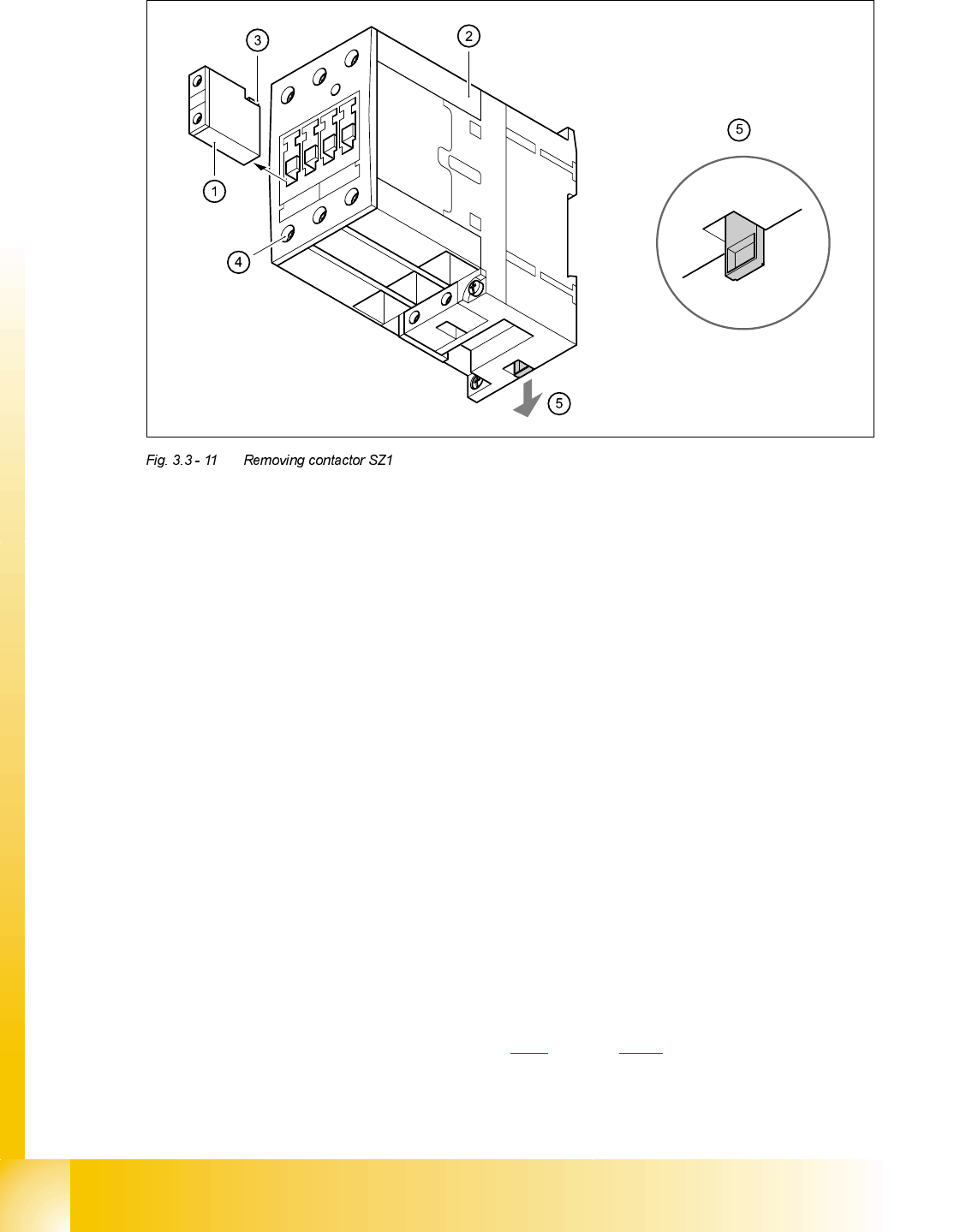
5HPRYLQJFRQWDFWRU6=
DANGER Switch off the placement system and disconnect from the power
supply (see sections 3.3.1 and 3.3.2).
07/2002 Edition Student Guide HS-50 Advanced II
3 Power Supply
38
➠ Remove auxiliary contact blocks K11, K12 and K14 from contactor SZ1.
➠ To do this, push the lug (3) on the top of the auxiliary contact block towards the front panel and
hold in place.
➠ Raise the auxiliary contact blocks (1) and remove from the slots.
➠ Loosen the clamping screws (4) on contactor SZ1.
➠ Pull the terminal wires out one by one and identify with adhesive labels.
➠ Use the screwdriver to press down the locking lug (5) on the back of the contactor.
➠ Tilt the contactor upwards and detach from the top-hat rail.
)LWWLQJFRQWDFWRU6=
➠ Attach the contactor to the top edge of the top-hat rail.
➠ Push down on the contactor until it snaps into place.
➠ Check that it is firmly seated.
➠ Connect up the terminal wires.
➠ Insert auxiliary contact blocks K11, K12 and K14 from the top and snap into place.
➠ Switch the placement system on.
➠ Test the 24 VDC control voltage between terminals A1 and A2.
➠ Test the supply voltage between terminals L1, L2, L3 and T1, T2 and T3.
➠ Complete the servicing work as described in 3.3.3 on page 3 - 29.