HS50_advance_level 2.pdf - 第78页
07/2002 Editio n Student G uide HS -50 Advanc ed II 3 Power Sup ply 40 ➠ Remove the auxi liary con tact blocks ➠ Push the lug ( 1) at the to p of the auxili ary contact bl ocks to wards the front panel a nd hol d in pl a…
Student Guide HS-50 Advanced II 07/2002 Edition
3 Power Supply
39
5HSODFLQJFRQWDFWRUV6=6=DQG6=
7RROVDQGHTXLSPHQW
– Set of slotted-head screwdrivers
– Self-adhesive labels
– Digital multimeter
– HS-50 detailed circuit diagrams
3DUWV
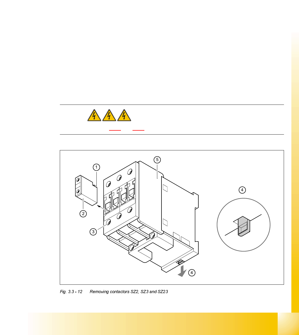
5HPRYLQJFRQWDFWRUV6=6=DQG6=
DANGER Switch off the placement system and disconnect from the power
supply (see sections 3.3.1 and 3.3.2).
&RQWDFWRU 'HVLJQDWLRQ ,WHPQXPEHU
SZ2 SIRIUS 3RT10/24 VDC, size S0 00341208-01
SZ3 SIRIUS 3RT10/24 VDC, size S0 00341208-01
SZ23 SIRIUS 3RT10/24 VDC, size S0 00341208-01

07/2002 Edition Student Guide HS-50 Advanced II
3 Power Supply
40
➠ Remove the auxiliary contact blocks
➠ Push the lug (1) at the top of the auxiliary contact blocks towards the front panel and hold in
place.
➠ Lift the auxiliary contact blocks (2) and remove from their slots.
➠ Loosen the contactor clamping screws (3).
➠ Pull the terminal wires out one by one and identify with adhesive labels.
➠ Use the screwdriver to press down the locking lug (4) on the back of the contactor.
➠ Tilt the contactor (5) upwards and detach from the top-hat rail.
)LWWLQJFRQWDFWRUV6=6=DQG6=
➠ Attach the contactor to the top edge of the top-hat rail.
➠ Push down on the contactor until it snaps into place.
➠ Connect up the terminal wires.
➠ Snap the auxiliary contact blocks into place on SZ2, SZ3 and SZ23.
➠ Switch the placement system on and start it up, then measure the voltages shown in the table
in section 3.2.2.2
on page 3 - 12.
➠ Complete the servicing work as described in 3.3.3 on page 3 - 29.
5HSODFLQJDX[LOLDU\FRQWDFWEORFNV.[.[.[
7RROVDQGHTXLSPHQW
– Set of slotted-head screwdrivers
– Self-adhesive labels
– Digital multimeter
– HS-50 detailed circuit diagrams
3DUWV
K21, K22, K23, K24 from SZ2
K31, K32, K33, K34 from SZ3
K232, K234 from SZ23
'HVLJQDWLRQ ,WHPQXPEHU
Auxiliary contact block 3RT1/1-pole/1 NC 00341210-01
(K11, K12, K24, K34, K234)
Auxiliary contact block 3RT1/1-pole/1 NO 00341221-01
(K14, K21, K22, K23, K31, K32, K33, K232)
Student Guide HS-50 Advanced II 07/2002 Edition
3 Power Supply
41
PLEASE NOTE
The 3RT1/1-pole/1NC auxiliary contact block has a normally closed contact. The terminals are
designated 1 NC and 2NC (NC = normally closed contact).
The 3RT1/1-pole/1NO auxiliary contact block has a normally open contact. The terminals are des-
ignated 3NO and 4NO (NO = normally open contact).
3RVLWLRQRIWKHDX[LOLDU\FRQWDFWEORFNV
5HPRYLQJWKHDX[LOLDU\FRQWDFWEORFN
DANGER Switch off the placement system and disconnect from the power
supply (see sections 3.3.1 and 3.3.2).
$X[LOLDU\FRQWDFWEORFN &RQWDFWRU
K11, K12 normally closed SZ1
K14, normally open SZ1
K24, normally closed SZ2
K21, K22, K23, normally open SZ2
K34, normally closed SZ3
K31, K32, K33, normally open SZ3
K234, normally closed SZ23
K232, normally open SZ23