HS50_advance_level 2.pdf - 第80页
07/2002 Editio n Student G uide HS -50 Advanc ed II 3 Power Sup ply 42 ➠ Loose n the clam ping sc rews (1). ➠ Pull the terminal wires u p or d own to rem ove and i dentify with adhe sive labels. ➠ Push the g rey lug a …
Student Guide HS-50 Advanced II 07/2002 Edition
3 Power Supply
41
PLEASE NOTE
The 3RT1/1-pole/1NC auxiliary contact block has a normally closed contact. The terminals are
designated 1 NC and 2NC (NC = normally closed contact).
The 3RT1/1-pole/1NO auxiliary contact block has a normally open contact. The terminals are des-
ignated 3NO and 4NO (NO = normally open contact).
3RVLWLRQRIWKHDX[LOLDU\FRQWDFWEORFNV
5HPRYLQJWKHDX[LOLDU\FRQWDFWEORFN
DANGER Switch off the placement system and disconnect from the power
supply (see sections 3.3.1 and 3.3.2).
$X[LOLDU\FRQWDFWEORFN &RQWDFWRU
K11, K12 normally closed SZ1
K14, normally open SZ1
K24, normally closed SZ2
K21, K22, K23, normally open SZ2
K34, normally closed SZ3
K31, K32, K33, normally open SZ3
K234, normally closed SZ23
K232, normally open SZ23
07/2002 Edition Student Guide HS-50 Advanced II
3 Power Supply
42
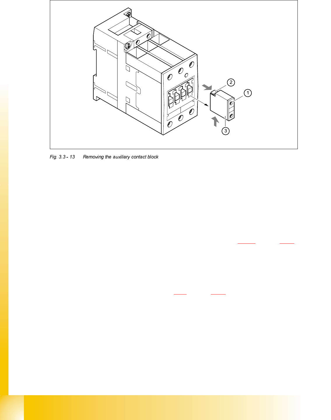
➠ Loosen the clamping screws (1).
➠ Pull the terminal wires up or down to remove and identify with adhesive labels.
➠ Push the grey lug at the top of the auxiliary contact block (2) towards the front panel and hold
in place.
➠ Raise the auxiliary contact block (3) and remove from the slots.
)LWWLQJWKHDX[LOLDU\FRQWDFWEORFN
➠ Check the type of the new auxiliary contact block (see table in section 3.3.9.2 on page 3 - 40).
➠ Insert the auxiliary contact block from the top.
➠ Attach the cable.
➠ Switch the placement system on and start it up, then measure the voltages at the auxiliary con-
tact blocks as per circuit diagram 00336145-XXXXXxLD4.
➠ Complete the servicing work as described in 3.3.3 on page 3 - 29.
5HSODFLQJFRQWDFWRU6=
7RROVDQGHTXLSPHQW
– Set of slotted-head screwdrivers
– Self-adhesive labels
– Digital multimeter
– HS-50 detailed circuit diagrams

Student Guide HS-50 Advanced II 07/2002 Edition
3 Power Supply
43
3DUWV
5HPRYLQJFRQWDFWRU6=
DANGER Switch off the placement system and disconnect from the power
supply (see sections 3.3.1 and 3.3.2).
➠ Remove the suppressor diode Di1 from contactor SZ4.
➠ Loosen the contactor clamping screw (1).
➠ Pull the terminal wires out one by one and identify with adhesive labels.
➠ Insert a screwdriver into the opening (2) in the plastic retainer and lift up slightly.
➠ Tilt the contactor down slightly and remove.
)LWWLQJFRQWDFWRU6=
➠ Place the contactor on the top of the top-hat rail and snap into place.
➠ Connect up the terminal wires.
➠ Fit the suppressor diode Di1.
&RQWDFWRU 'HVLJQDWLRQ ,WHPQXPEHU
SZ4 SIRIUS 3RT13/24 VDC, size S0 00341209-01
Di1 Suppressor diode for contactor SZ4/DL 24-70V 00342396-01