HS50_advance_level 2.pdf - 第84页
07/2002 Editio n Student G uide HS -50 Advanc ed II 3 Power Sup ply 46 5HSODF LQJFLU FXLWEUHDNH U0606 7 RROV DQGHTXLSPHQW – Set of slotte d-head s crewdriv ers – Self-ad hesive l…
Student Guide HS-50 Advanced II 07/2002 Edition
3 Power Supply
45
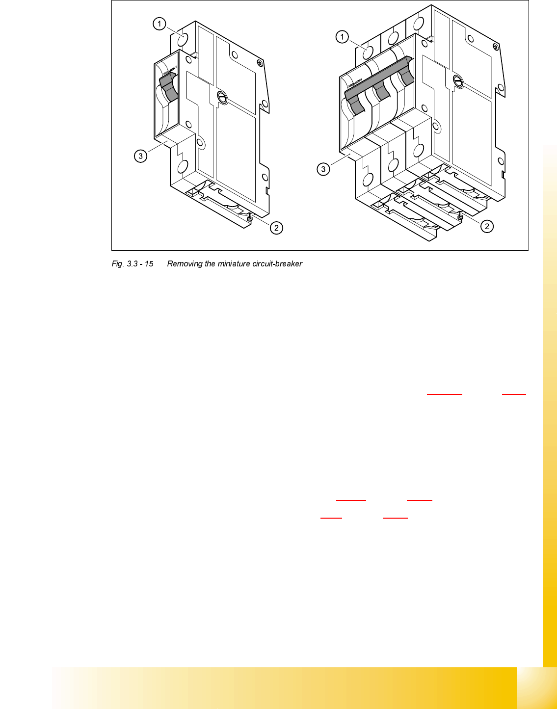
➠ Loosen the clamping screw (1).
➠ Pull out the terminal wires.
➠ Use the screwdriver to press the hook (2) downwards and hold it in this position.
➠ Tilt the miniature circuit-breaker (3) upwards and remove.
)LWWLQJWKHPLQLDWXUHFLUFXLWEUHDNHU
➠ Check the type of miniature circuit-breaker against the table in section 3.3.10.2 on page 3 - 43.
➠ Attach the miniature circuit-breaker to the top of the top-hat rail.
➠ Press down on the miniature circuit-breaker so that it snaps in place.
➠ Check that it is firmly seated.
➠ Connect up the terminal wires.
➠ Switch the placement system on and start it up.
➠ Measure the voltages as per the table in section 3.2.2.2 on page 3 - 12.
➠ Complete the servicing work as described in 3.3.3 on page 3 - 29.
07/2002 Edition Student Guide HS-50 Advanced II
3 Power Supply
46
5HSODFLQJFLUFXLWEUHDNHU0606
7RROVDQGHTXLSPHQW
– Set of slotted-head screwdrivers
– Self-adhesive labels
– Digital multimeter
– HS-50 detailed circuit diagrams
3DUWV
MS3, MS4, MS5, MS6 circuit-breaker 3RV10/0.45 - 0.63 A, item number 00342491-01
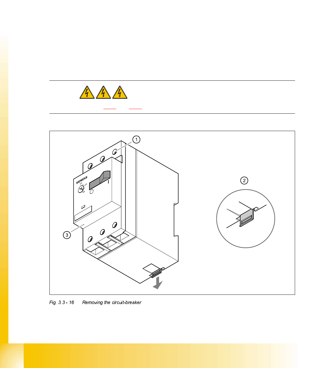
5HPRYLQJFLUFXLWEUHDNHU0606
DANGER Switch off the placement system and disconnect from the power
supply (see sections 3.3.1 and 3.3.2).
Student Guide HS-50 Advanced II 07/2002 Edition
3 Power Supply
47
➠ Loosen the clamping screws (1). Pull the terminal wires out one by one and identify with adhe-
sive labels.
➠ Press down on the lug (2) on the back of the circuit-breaker (3).
➠ Tilt the circuit-breaker (3) upwards slightly and remove.
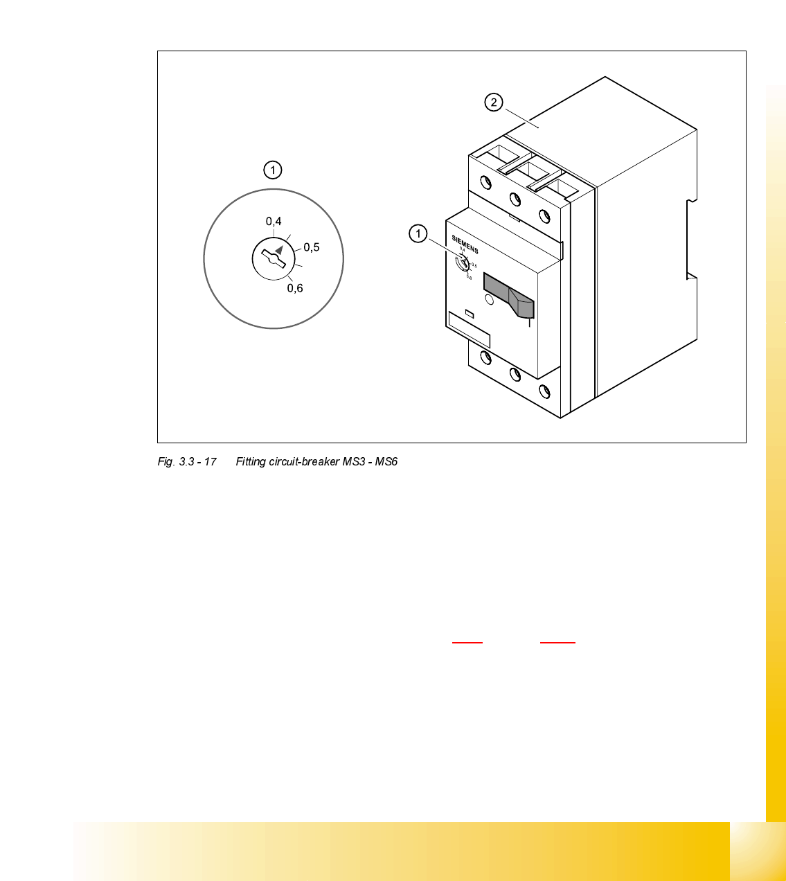
)LWWLQJFLUFXLWEUHDNHU0606
➠ Set the thermal overload current on the dial (1) to 0.45 A.
➠ Place the circuit-breaker (2) on the top-hat rail and snap into place.
➠ Connect up the terminal wires.
➠ Switch the placement system on and start it up.
➠ Use the digital voltmeter to measure the 3 x 230 VAC supply at input terminals 1, 3, 5 and out-
put terminals 2, 4 and 6.
➠ Complete the servicing work as described in 3.3.3 on page 3 - 29.