HS50_advance_level 2.pdf - 第95页
Stud ent Gu ide HS-5 0 Adva nced II 07/2 002 Ed ition 3 Power Supply 57 3DUWV 5HPRYLQJ (/5RU(/5 DANGER Switc h off the plac ement sy stem and disconn ect from the po wer suppl y (see section s 3.3…
07/2002 Edition Student Guide HS-50 Advanced II
3 Power Supply
56
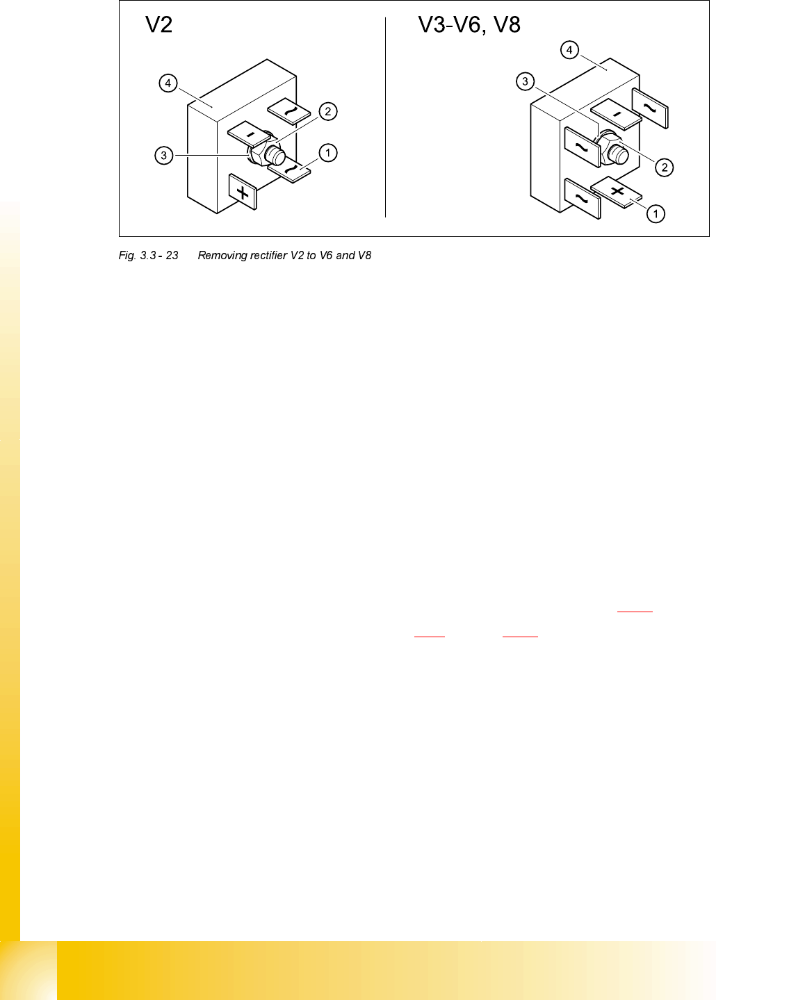
➠ Detach the cable lugs (1) from the terminal links one by one and identify the terminal wires with
self-adhesive labels.
➠ Loosen the M6 hexagon head screw (2) and remove the retaining ring (3).
➠ Remove the rectifier (4).
➠ Remove residue of heat transfer compound from the surfaces of the unit.
)LWWLQJUHFWLILHU9WR9DQG9
➠ Apply heat transfer compound to the "metal side" of the rectifier.
➠ Fit the rectifier (4) and retaining ring (3).
➠ Fix the rectifier in place with the M6 hexagon head screw (2).
➠ Attach the cable lugs, ensuring that the polarity is correct.
➠ Switch the placement system on and start it up.
➠ Measure the voltages as per the table "Voltages at rectifiers V1 - V8" on page 3 - 16.
➠ Complete the servicing work as described in 3.3.3 on page 3 - 29.
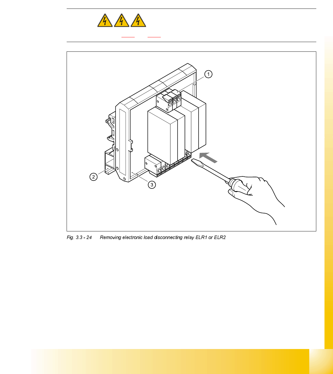
5HPRYLQJHOHFWURQLFORDGGLVFRQQHFWLQJUHOD\(/5RU(/5
7RROVDQGHTXLSPHQW
– Set of slotted-head screwdrivers
– Digital multimeter
– HS-50 detailed circuit diagrams
Student Guide HS-50 Advanced II 07/2002 Edition
3 Power Supply
57
3DUWV
5HPRYLQJ(/5RU(/5
DANGER Switch off the placement system and disconnect from the power
supply (see sections 3.3.1 and 3.3.2).
➠ Use the screwdriver to push back the yellow (1) terminal link slightly.
➠ Pull the terminal wires out one by one and identify with adhesive labels.
➠ Use the screwdriver to press down the two locking lugs (2) on the back and remove ELR1 (3)
or ELR2 from the top-hat rail.
)LWWLQJ(/5RU(/5
➠ Place ERL1 and/or ERL2 on the top-hat rail and snap into place.
➠ Check that it is firmly seated.
➠ Connect the marked terminal wires. Ensure that they are firmly attached.
3RVLWLRQ 'HVLJQDWLRQ ,WHPQXPEHU
ELR1, ELR2 (Fig. 5.8.2) Board ARL TC 31034-01 00341835-01
07/2002 Edition Student Guide HS-50 Advanced II
3 Power Supply
58
➠ Switch the placement system on and start it up.
➠ Use the digital voltmeter to measure the voltages.
➠ Complete the servicing work as described in 3.3.3 on page 3 - 29.
5HSODFLQJHOHFWURO\WLFFDSDFLWRU&
7RROVDQGHTXLSPHQW
– Set of slotted-head screwdrivers
– Set of Phillips screwdrivers
– Self-adhesive labels
– Digital multimeter
– HS-50 detailed circuit diagrams
3DUWV
5HPRYLQJWKHHOHFWURO\WLFFDSDFLWRU
DANGER Switch off the placement system and disconnect from the power
supply (see sections 3.3.1 and 3.3.2).
9ROWDJH %HWZHHQFRQWDFWV
Control voltage 9 - 10
24 VDC 11 - 10
230 VAC 1 - 3, 2 - 4
5 - 7, 6 - 8
3RVLWLRQ 'HVLJQDWLRQ ,WHPQXPEHU
C1 Electrolytic capacitor 33000 µF/63 V 00342399-01