00197089-02_AI_EA-Verl_X-Serie_S_de_en - 第45页
Introduction 1.1.4 Safety Instructions for the Gantry Safety Instructions Extension Input/Output Conveyor and Hand Guard Ein-/Ausga beband verlängerung und Eingreifschutz 45 1.1.4 1 . 1 . 4 S a f e t y I n s t r u c t io…

Introduction
Safety Instructions 1.1.2 Safety Instructions for Working with Strong Magnetic Fields
44 Extension Input/Output Conveyor and Hand Guard Ein-/
1.1.2
1.1.2 Safety Instructions for Working with Strong Magnetic Fields
Safety Instructions for Working with Strong Magnetic Fields
1.1.3
1.1.3 Safety Instructions for the Power Supply
Safety Instructions for the Power Supply
▪ This means that some parts of the system carry potentially lethal voltages - even when switched off
at the main power switch.
▪ Incorrect handling of the placement system can therefore result in fatal injuries, severe injuries or
considerable damage to equipment.
▪ Measurements and maintenance work must always be carried out by appropriately qualified person-
nel.
▪ Always follow the applicable accident prevention and DIN regulations (particularly DIN EN 60 204,
part 1) or the regulations specific to your country.
▪ Before starting any maintenance work, switch the machine off at the main switch and disconnect it
from the main power supply.
▪ Always secure the machine against unauthorized reactivation. If these instructions are not followed,
you may be able to touch live parts, which could result in fatal or severe injuries.
Maintaining or Replacing Assemblies
► End all placement operations on the machine.
► Shut down the Windows operating system correctly, otherwise problems may occur when restarting
or data may be lost.
► Switch the machine off at the main switch.
► Disconnect the machine from the main power supply.
► Switch off the machine and attach warnings signs to indicate that service work is in progress.
DANGER
Strong permanent magnet fields
Fatal hazard: persons with active implants (e.g. pacemakers, defibrillators, insulin pumps etc.)
are at risk from strong permanent magnetic fields inside the machine.
Persons at risk should avoid the immediate vicinity of the machine.
CAUTION
Danger of crushing
Danger of crushing for persons with passive metal implants (e.g. plates, screws).
► Do not reach or lean over into the machine when the protective covers are open.
► Do not bring any metal objects into the hazard area.
CAUTION
Strong permanent magnet fields
There is a risk that the strong magnetic fields could corrupt data on data media or check cards.
► Keep sensitive data supports away from the permanent magnets.
WARNING
Hazardous Voltages!
The machine is supplied with 3 x 400 V~ (or. 3 x 204 V~ / 3 x 220 V~ / 3 x 230 V~ / 3 x 380 V~
/ 3 x 415 V~) ± 5 %, 50/60 Hz mains voltages.
► Observe the safety instructions in the user manual during all service work!

Introduction
1.1.4 Safety Instructions for the Gantry Safety Instructions
Extension Input/Output Conveyor and Hand Guard Ein-/Ausgabebandverlängerung und Eingreifschutz 45
1.1.4
1.1.4 Safety Instructions for the Gantry
Safety Instructions for the Gantry
1.1.5
1.1.5 Safety Instructions on Hazardous Materials
Safety Instructions on Hazardous Materials
CAUTION
Moving the gantry can damage the placement head.
When moving the gantry, observe the following:
► NEVER move the gantry by pushing with your hands against the placement head.
► NEVER push the gantry while the Z axis is lowered.
CAUTION
Observe the safety data sheets
Observe the applicable safety data sheet, when handling hazardous materials (e. g. Loctite
241, ethanol).
Introduction
Safety Instructions 1.1.6 Laser Classification
46 Extension Input/Output Conveyor and Hand Guard Ein-/
1.1.6
1.1.6 Laser Classification
Laser Classification
1.1.6.1
1.1.6.1 Laser Class 1
Laser Class 1
Classification of the Whole Machine
Classification of the Camera Systems
1.1.6.2
1.1.6.2 Laser Class 1M
Laser Class 1M
1.1.6.3
1.1.6.3 Laser class 2
Laser class 2
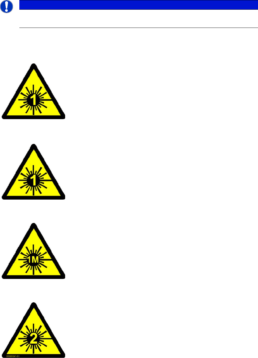
NOTICE
Laser class 1 and 1M
Modules in laser classes 1 and 1M are not labeled.
All installed camera systems and the whole machine (when ready for oper-
ation) are assigned to laser class 1.
The laser classes are determined according to DIN EN 60825-1:2001.
The following camera systems are assigned to laser class 1:
▪ Stationary component cameras for the SIPLACE TwinStar (TwinHead)
and the SIPLACE Multistar (CPP)
▪ Component camera, stationary, P&P, type 33, 55 x 45, digital
▪ Component camera, stationary, P&P, type 25, 16 x 16, digital
▪ Component camera, stationary, P&P, type 36, 32 x 32, digital
Do not look directly at this with optical instruments!
The following camera systems are assigned to laser class 1M:
▪ CO camera C&P, type 23, 6 x 6 on the SpeedStar
▪ CO camera C&P, type 41, 6 x 6 on the SpeedStar
▪ CO camera C&P, type 30, 27 x 27 on the MultiStar
▪ CO camera C&P, type 30, 18 x 18 on the 12-segment Collect&Place
head
Laser radiation
Do not look into beam!
The following modules are assigned to laser class 2:
▪ PCB barcode scanner
▪ Component sensor on the SpeedStar
▪ Component sensor on the MultiStar
The entire machine is classified as laser class 2 if the coplanarity laser mod-
ule option is installed.