00197089-02_AI_EA-Verl_X-Serie_S_de_en - 第69页
Installation 3.2.8 Output Conveyor – Conveyor Side D Assembly of Input/Output Conveyor Extension Extension Input/Output Conveyor and Hand Guard Ein-/Ausga beband verlängerung und Eingreifschutz 69 3.4 3 . 4 A s s e m b l…
Installation
Preparatory Steps 3.2.8 Output Conveyor – Conveyor Side D
68 Extension Input/Output Conveyor and Hand Guard Ein-/
3.3
3.3 Preparatory Steps
Preparatory Steps
► Use the software to move the conveyor sides into the position which allows you best access. Alter-
natively, you can also loosen the conveyor side clamps on the dual conveyor. (see service manual)
► Switch off the machine, disconnect it from the power supply and secure it to prevent unauthorized
reactivation. Observe the instructions in section "1.2 Preparatory Work..." [ ➙ 47].
► To improve access to the single conveyor, you may want to loosen the screws fastening the fixed
side and move this to the center of the conveyor.
NOTICE
Tip
Conveyor configuration: 268 mm outer, both lanes approx. 200 mm width
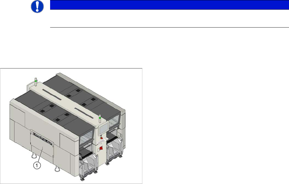
► Dismantle any standard hand guard (1). Loosen the
4 fastening screws to do this. Then remove the bolts
behind.
Installation
3.2.8 Output Conveyor – Conveyor Side D Assembly of Input/Output Conveyor Extension
Extension Input/Output Conveyor and Hand Guard Ein-/Ausgabebandverlängerung und Eingreifschutz 69
3.4
3.4 Assembly of Input/Output Conveyor Extension
Assembly of Input/Output Conveyor Extension
NOTICE
Observe the detailed diagrams: differences between the input/output conveyor extension
The conversion is, in principle, the same in all cases. However, some details differ between in-
put and output conveyor extensions. There are also differences between the individual convey-
or sides.
► When performing conversion work, observe all relevant diagrams in section "3.2 Overview
of Conversion (Before/After)" [ ➙ 60].
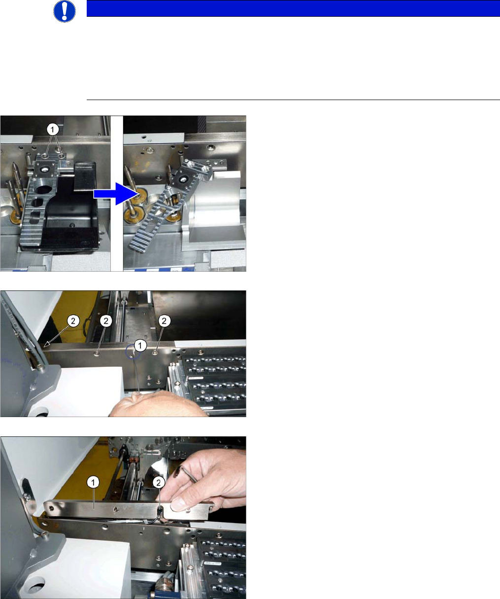
► Output conveyor only:
To improve access for dismantling the belt guidance,
you may want to also remove the nozzle reject sta-
tion. In this case, loosen the two fastening screws (1)
and turn the nozzle reject station to one side.
► Loosen the sensor screw (1) on the belt guidance.
► Loosen the three screws (2) (TX25) fastening the belt
guidance.
► Take the belt guidance (1) off the side. To do this,
carefully pull the sensor (2) out of the belt guidance.
Please also observe the relevant diagram in section
"3.2 Overview of Conversion (Before/After)" [ ➙ 60].
Installation
Assembly of Input/Output Conveyor Extension 3.2.8 Output Conveyor – Conveyor Side D
70 Extension Input/Output Conveyor and Hand Guard Ein-/
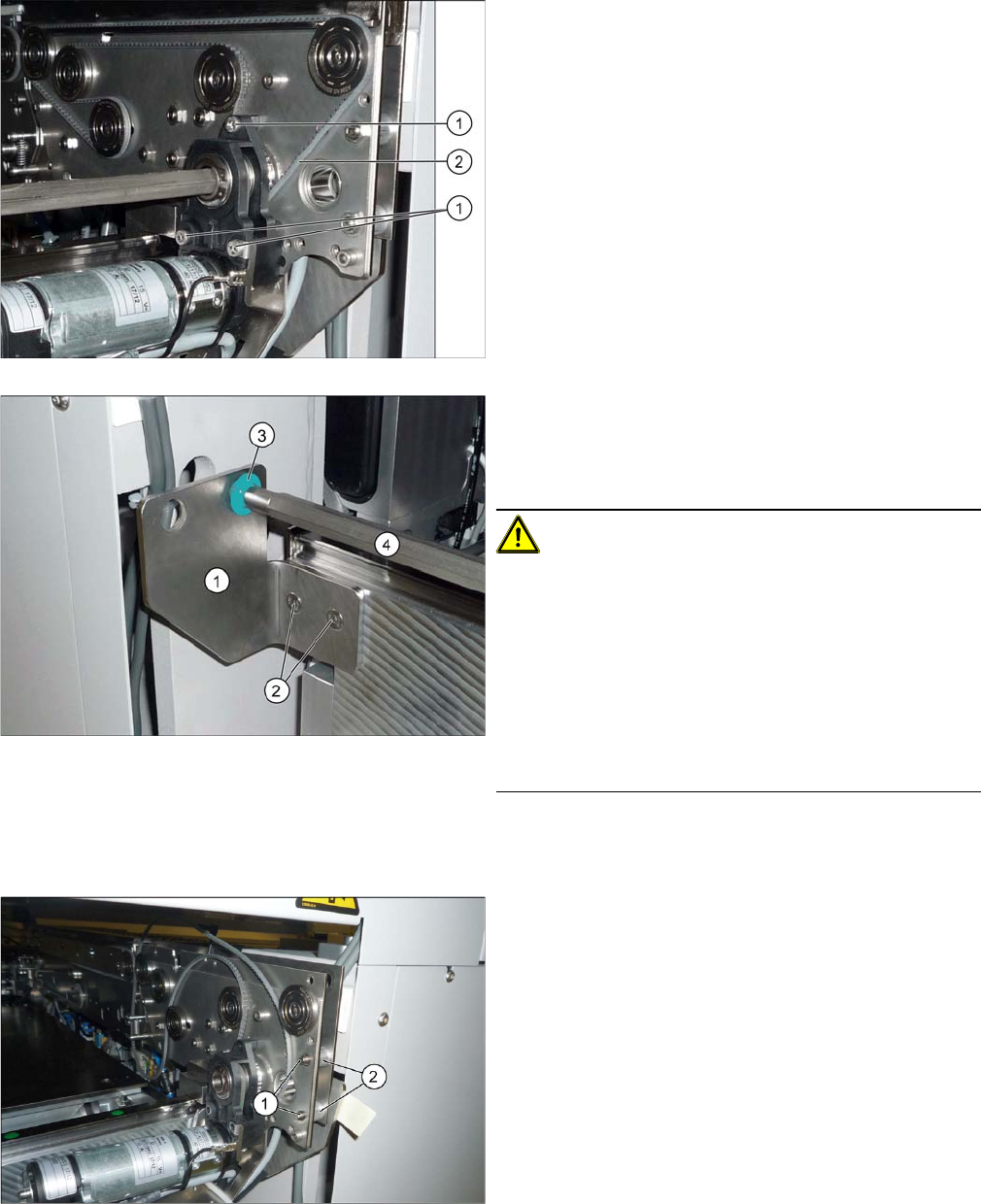
► Loosen the three screws (1) fastening the drive/mo-
tor.
► Push the drive/motor on the hexagonal shaft off the
side. While doing so, unthread the conveyor belt (2).
► Loosen the screws (2) fastening the hexagonal shaft
bracket (1) and remove these. You can dismantle ei-
ther the left or right hexagonal shaft fixture, depend-
ing on the ease of access.
CAUTION!
The hexagonal shafts are fixed on both sides of the con-
veyor with brackets.
Make sure that you do not lose the plastic bearings (3).
When you dismantle a bracket, always remove all the
plastic bearings on this and the bracket opposite. These
would otherwise obstruct movement of the hexagonal
shafts and could easily fall out.
The plastic bearings can be re-ordered by quoting the
number [03092024-xx].
► Move the hexagonal shaft (4) and unthread the con-
veyor belt.
► Loosen the two fastening screws (1) (TX25) incl.
counternuts (if present) at the end of the side and
then remove the spacers (2).
Observe the relevant diagram in section "3.2 Over-
view of Conversion (Before/After)" [ ➙ 60].