00197089-02_AI_EA-Verl_X-Serie_S_de_en - 第72页
Installation Assembly of Input/Output Conveyor Extension 3.2.8 Output Conveyo r – Conveyor Side D 72 Extension Input/Output Conveyor and Hand Guard Ein-/ ► Thread the conveyor belt into t he d eflection pulleys and fix i…
Installation
3.2.8 Output Conveyor – Conveyor Side D Assembly of Input/Output Conveyor Extension
Extension Input/Output Conveyor and Hand Guard Ein-/Ausgabebandverlängerung und Eingreifschutz 71
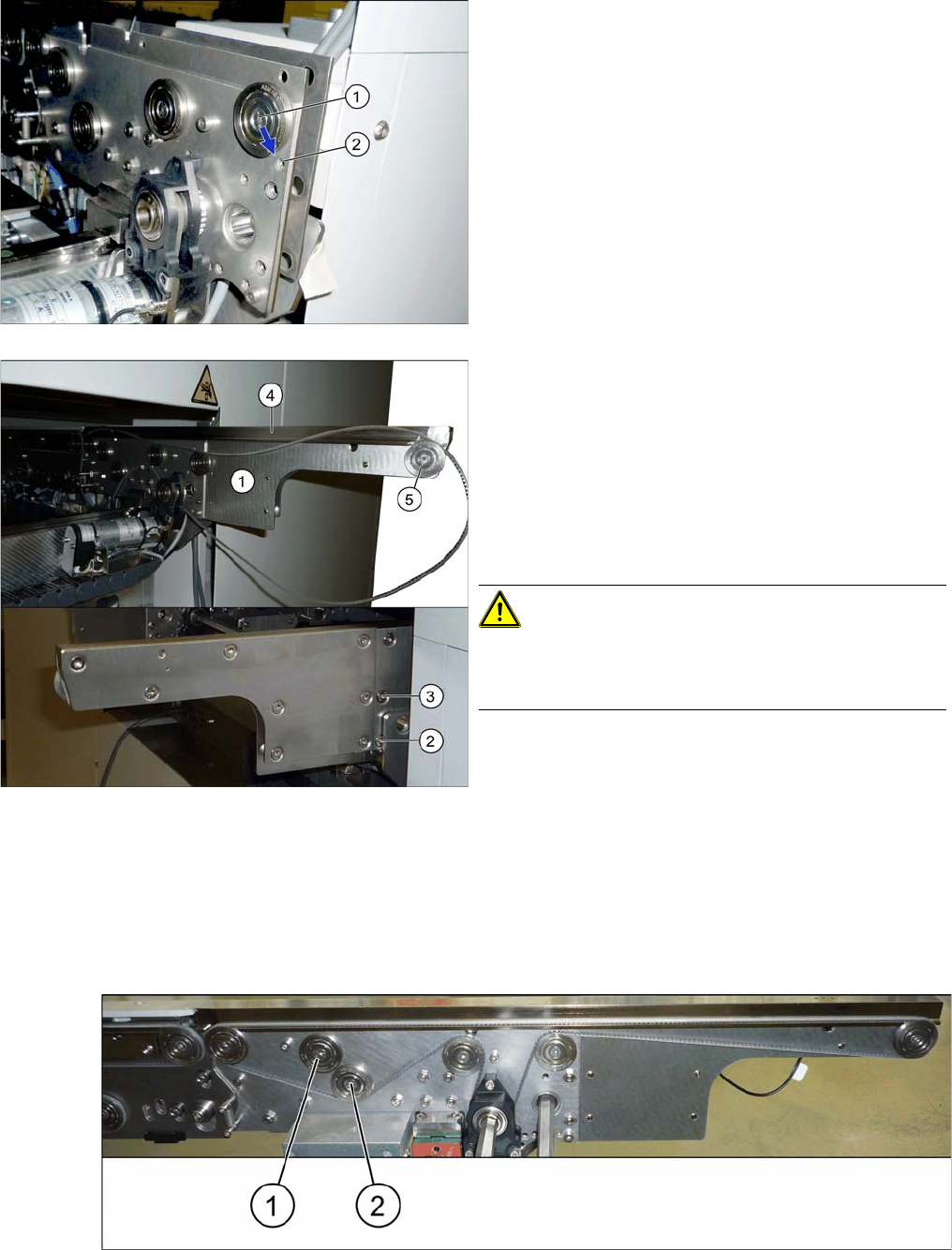
► Use 6 screws (TX25) to fasten the new belt guidance. Tighten these with a torque of 6 Nm.
► Fix the sensor with the grub screw. (careful: plastic!)
► If not prefitted, fit the deflection pulley to the end of the side, together with the conveyor belt.
► Thread the conveyor belt into the drive/motor.
► Fasten the drive/motor with the three fastening screws. Press the drive/motor slightly upwards while
doing this. (careful: plastic!)
► Output conveyor only (all sides):
Move the idler no longer needed (1) right up to the center of the machine. It must not touch the new
idler (2).
► Move the deflection pulley from (1) to (2). To do this,
loosen the screw fastening the deflection pulley and
fix this to its new position.
Also observe the relevant diagram in section "3.2
Overview of Conversion (Before/After)" [ ➙ 60].
► Insert the lower section (1) at the end of the side.
► Fix the lower section to the points marked (2) and (3)
(TX25). The screws used may differ according to the
conveyor side (some may be with counternuts).
Also observe the relevant diagram in section "3.2
Overview of Conversion (Before/After)" [ ➙ 60].
► Insert the sensor into the new belt guidance (4).
► Position the new belt guidance onto the side.
CAUTION!
Take care when running the fiber optic cable. Make sure
that is is not bent or damaged. Pay particular attention to
the area between the input and output conveyor..
Installation
Assembly of Input/Output Conveyor Extension 3.2.8 Output Conveyor – Conveyor Side D
72 Extension Input/Output Conveyor and Hand Guard Ein-/
► Thread the conveyor belt into the deflection pulleys and fix into place with the idler. For details of the
exact routing of the belt, refer to the diagrams in section "3.2 Overview of Conversion (Before/After)"
[➙60].
► Repeat these steps for all conveyor sides.
► Push the hexagonal shaft back to its original position and fix the hexagonal shaft bracket into place
with the plastic bearings. Retighten the fastening screws manually (hand-tight).
► Set the belt tensions at all new and loosened belts. For details of the correct values, refer to the rel-
evant diagrams in section "3.2 Overview of Conversion (Before/After)" [ ➙ 60].
Also observe section "4.1 Calculating the Belt Tension" [ ➙ 77].
CAUTION
Output conveyor (all sides)
Make sure that the old and new idlers do not touch one another.
► If the two idlers do touch after the belt tension has been set, check the position of the motor/
drive. This should be pressed slightly upwards during assembly. This allows the conveyor
belt enough play.
Installation
3.2.8 Output Conveyor – Conveyor Side D Fitting the Hand Guard
Extension Input/Output Conveyor and Hand Guard Ein-/Ausgabebandverlängerung und Eingreifschutz 73
3.5
3.5 Fitting the Hand Guard
Fitting the Hand Guard
NOTICE
Second person
► You may need to enlist the help of a second person for this job.
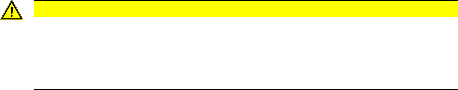
► Fix the hand guard into place on the machine, using
the 4 fastening screws (1). (washer M6, screw
[03042571-xx] M6x10)
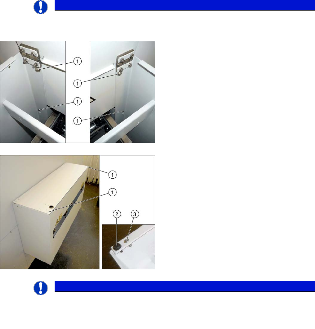
Without PCB barcode:
If no PCB barcode has been fitted, this flap must be
screwed into place. Proceed as follows:
► Make sure that the two buffers (2) are fitted.
► Fix the flap to the two corners (1) using the screws
provided (3).
The installation of the hand guard is completed.
NOTICE
With PCB barcode:
If a PCB barcode is fitted into the hand guard, make sure you secure the flap with a Schmersal
switch.
► Read the "PCB Barcode" assembly instructions.