ASM_MANUAL_TYPHOON_USC_en_100620_online.PDFA - 第13页
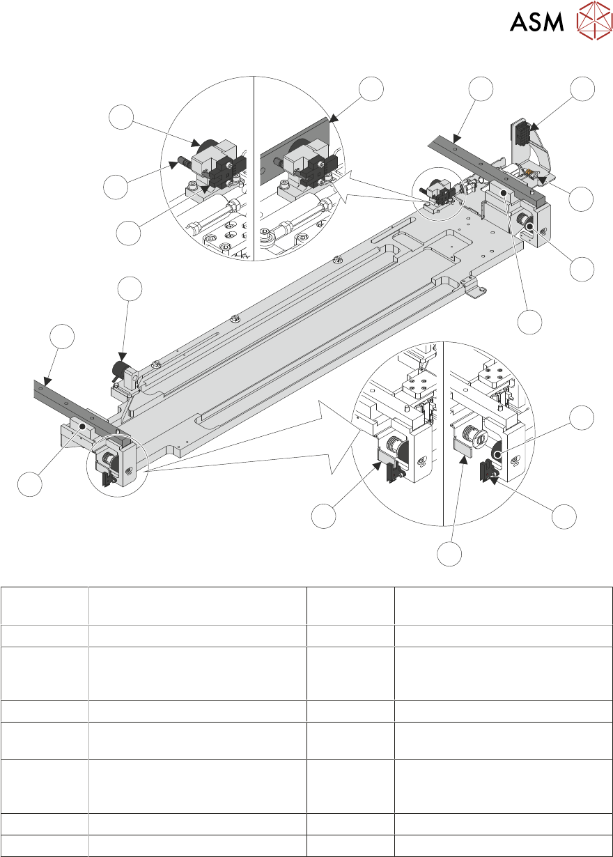
3 TYPHOON UNDER STENCIL CLEANER 3.2 USC ASSEMBLIES STANDALONE MANUAL TYPHOON UNDER STENCIL CLEANER 06/2020 13 1 2 3 4 9 10 1 1 16 5 6 7 8 12 13 14 15 1 Power and Control Loom Connector 9 Left-Hand End Linear Bearing 2 Ea…

3 TYPHOON UNDER STENCIL CLEANER
3.2 USC ASSEMBLIES
12 STANDALONE MANUAL TYPHOON UNDER STENCIL CLEANER 06/2020
3.2 USC ASSEMBLIES
NOTE
The information and illustrations throughout the rest of this manual detail the standard version of
the Typhoon USC (300, 400, 460 and 515mm widths) but also apply to the Long Board (620mm)
version. The Long Board (620mm) version is only shown/mentioned where there is a recognisable
difference.
3.2.1 USC Base Unit
The base unit supports the other USC assemblies and attaches the USC to linear bearings (one
per end) which allow the USC to run along linear rails, when pulled by the camera carriage during
cleaning sweeps.
The right-hand end bracket connects to a drag-chain, which supplies all power and control looms,
pneumatics and solvent to the USC. This bracket also houses the earth stud.
Two home position electromagnets are fitted to the end of the linear rails, these become energized
to hold the USC in the home position. The left-hand end electromagnet has a through beam opto
sensor, which signals to the printer that the USC is in the home position when the associated vane
is detected.
Two camera carriage attachment electromagnets are fitted to the rear of the USC base unit. The
electromagnets attach the USC to the camera carriage, so it can be moved during cleaning
sweeps. The right-hand electromagnet has a through beam opto sensor, when the USC is attached
to the camera carriage the associated plunger/vane is pushed towards the sensor signaling to the
printer that the USC is attached. If, for any reason, the USC is not connected to the camera car-
riage when it should be, the lack of plunger/vane through the sensor signals to the printer that the
USC has been "detached".
3 TYPHOON UNDER STENCIL CLEANER
3.2 USC ASSEMBLIES
STANDALONE MANUAL TYPHOON UNDER STENCIL CLEANER 06/2020 13
1
2
3
4
9
10
11
16
5
6
7
8
12
13
14
15
1 Power and Control Loom
Connector
9 Left-Hand End Linear Bearing
2 Earth Stud 10 Left Linear Rail
3 Right-Hand Home
Electromagnetic Clamp
11 Left-Hand Camera Beam
Attachment Electromagnetic
Clamp
4 Right-Hand End Linear Bearing 12 USC Detached Sensor
5 Left-Hand Home Electromagnetic
Clamp
13 USC Detached Sensor Plunger/
Vane
6 USC Home Sensor 14 Right-Hand Camera Beam
Attachment Electromagnetic
Clamp
7 USC Vane 15 Camera Beam Magnetic Plate
8 USC Vane (Home Position) 16 Right Linear Rail
3 TYPHOON UNDER STENCIL CLEANER
3.2 USC ASSEMBLIES
14 STANDALONE MANUAL TYPHOON UNDER STENCIL CLEANER 06/2020
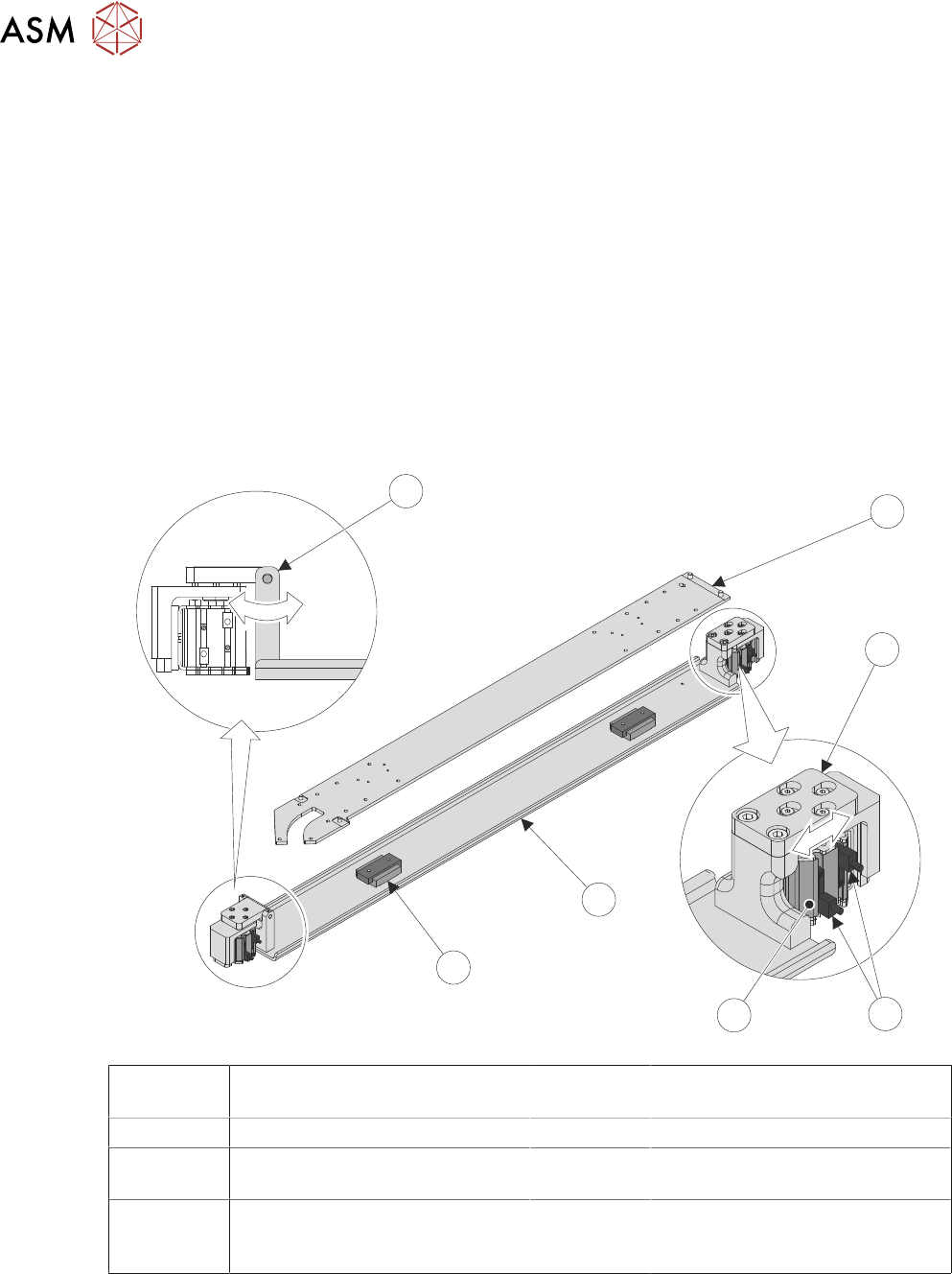
3.2.2 Lift Mechanism Assembly
The lift mechanism assembly raises and lowers the fabric roll and plenum chamber assembly dur-
ing the cleaning sweep. Two pneumatically powered lift actuators (one per end) lift and lower the
lifting plate and the assembly mounted on it.
The lift actuators can be optionally fitted with limit sensors (up and down limit) which can signal to
the printer software when a lift/lower activation fails (ie. the actuator is stuck).
NOTE
The limit sensors are not an option on the Long Board (620mm) USC.
In the event that one of the lift actuators gets stuck (either up or down), the left-hand actuator
bracket can pivot and the right-hand actuator top plate has enlarged screw holes allowing the lifting
plate to be stuck at an angle without causing any damage.
The chamber base is supported above the lifting plate on a pair of linear bearings.
NOTE
The linear bearings are not fitted on the Long Board (620mm) USC.
5
6
1
7
2
3
4
1 Fabric and Plenum Chamber
Assembly
5 Chamber Lift Actuator
(2 positions)
2 Plenum Chamber Base 6 Lifting Plate
3 Lift Actuator Top Plate 7 Chamber Base Bearing
(2 positions) - Standard USC only
4 Lift Actuator Home and Limit
Sensors (2 positions)
- Standard USC only
8 Lift Actuator Pivoting Bracket