ASM_MANUAL_TYPHOON_USC_en_100620_online.PDFA - 第34页
3 TYPHOON UNDER STENCIL CLEANER 3.8 ADJUSTMENTS AND SETTINGS 34 STANDALONE MANUAL TYPHOON UNDER STENCIL CLEANER 06/2020 3.8 ADJUSTMENTS AND SETTINGS P R O H I B I T I O N . E L E C T R O M A G N E T I C F I E L D . AN E …
3 TYPHOON UNDER STENCIL CLEANER
3.7 REPLACEMENT PROCEDURES
STANDALONE MANUAL TYPHOON UNDER STENCIL CLEANER 06/2020 33
3.7.2 Plenum Chamber
Plenum chambers for the Typhoon USC are available in 300mm, 400mm, 460mm, 515mm and
620mm widths to suit a variety of board lengths. To remove a chamber for cleaning, or to change
width to suit a different stencil/product, complete the following remove and replace procedures:
NOTE
As the Long Board (620mm) USC only has one width of chamber available, the following procedure
only applies to the standard USC.
3.7.2.1 Plenum Chamber Removal (Standard USC)
To remove the plenum chamber, carry out the following:
1. Ensure that 3.7.1.1 "Plenum Chamber Insert Removal" [}31] has been performed.
2. Remove the vacuum tube from the right-hand end of the USC assembly.
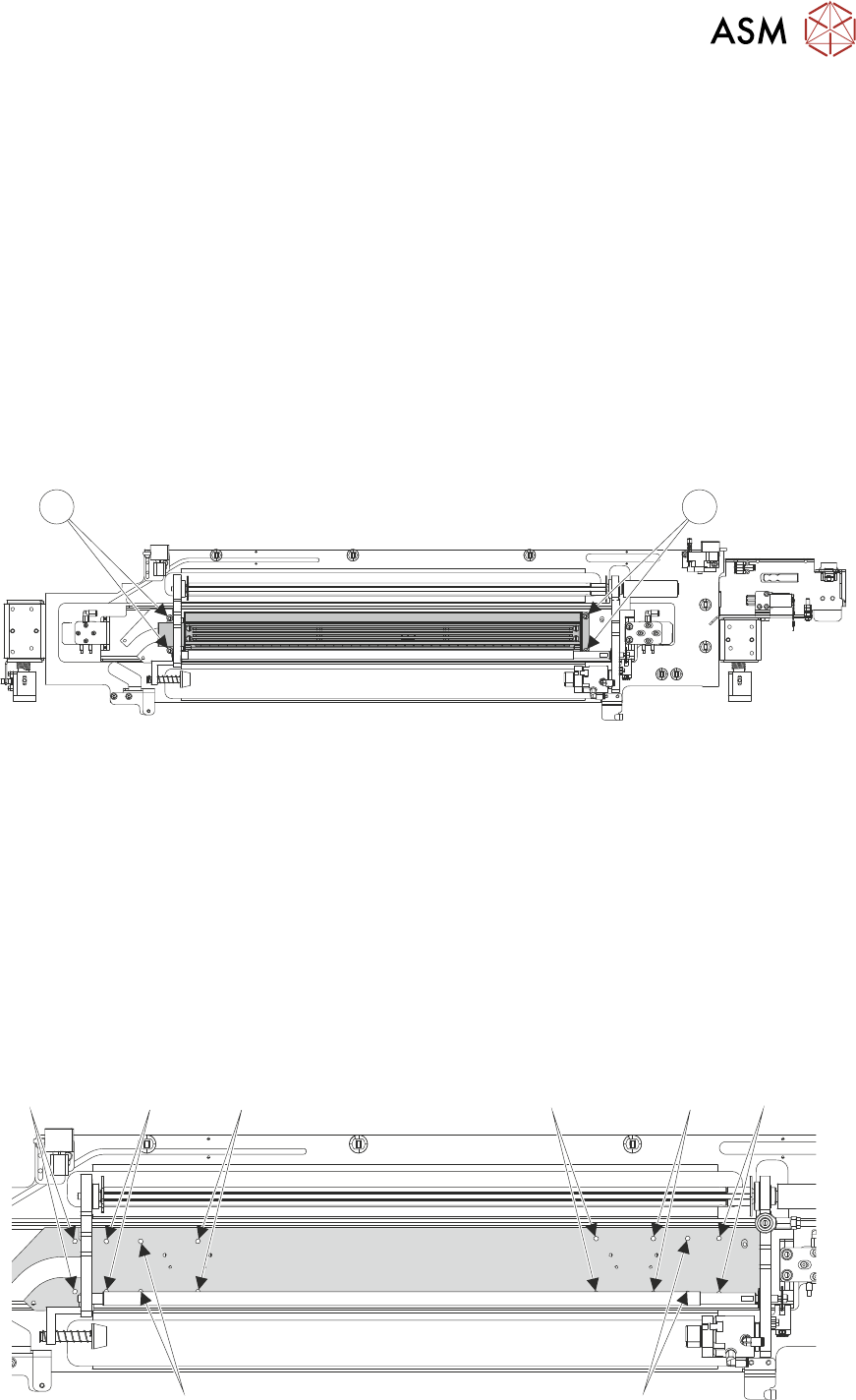
3. Remove and retain the four M5 socket cap head screws (1), which secure the plenum cham-
ber to the USC base.
1 1
4. Slide the plenum chamber towards the right-hand end of the USC assembly and lift away from
the base unit.
5. Remove the plenum chamber from the machine.
3.7.2.2 Plenum Chamber Replacement (Standard USC)
To install/reinstall the plenum chamber, carry out the following:
1. Place the plenum chamber onto the USC base.
2. Slide the plenum chamber towards the left-hand end of the USC.
3. Secure the plenum chamber to the USC base using the four M5 socket cap head screws re-
tained during 3.7.2.1 "Plenum Chamber Removal (Standard USC)" [}33]. (Illustration below
displays the screw holes to be used depending on width of plenum chamber.)
515mm
460mm 300mm
400mm
300mm
400mm 515mm
460mm
4. Connect the vacuum tube to the left-hand end of the USC assembly.

3 TYPHOON UNDER STENCIL CLEANER
3.8 ADJUSTMENTS AND SETTINGS
34 STANDALONE MANUAL TYPHOON UNDER STENCIL CLEANER 06/2020
3.8 ADJUSTMENTS AND SETTINGS
PROHIBITION.
ELECTROMAGNETIC FIELD. AN ELECTROMAGNETIC FIELD EXISTS WITHIN
THE MACHINE FROM THE LINEAR MOTORS. THESE MAY PRESENT A
HAZARD TO PEOPLE FITTED WITH AN IMPLANTED CARDIAC DEVICE.
THE MOTOR MANUFACTURER RECOMMENDS A SAFE DISTANCE OF AT
LEAST 400MM.
PROHIBITION.
STRONG MAGNETIC FIELD. A STRONG MAGNETIC FIELD EXISTS IN THE
VICINITY OF THE LINEAR MOTORS THAT REPRESENT A SERIOUS HAZARD
TO PEOPLE FITTED WITH METALLIC IMPLANTS.
PROHIBITION.
STRONG MAGNETIC FIELD. A STRONG MAGNETIC FIELD EXISTS IN THE
VICINITY OF THE LINEAR MOTORS THAT MAY ACT UPON FERROUS
OBJECTS WHOSE MOVEMENTS COULD LEAD TO PERSONAL INJURY
AND/OR DAMAGE TO THE MACHINE.
WARNING
STRONG MAGNETIC FIELD. A STRONG MAGNETIC FIELD EXISTS IN THE VICINITY
OF THIS LABEL. THIS MAY PRESENT A HAZARD TO PERSONNEL OR EQUIPMENT.
))
((
CAUTION
PRINT MEDIUM AND SOLVENTS. WHEN USING OR HANDLING ANY PRINT
MEDIUM OR SOLVENT FORMULATION THE MANUFACTURER’S SAFETY
DATA SHEETS MUST BE STRICTLY ADHERED TO.
MANDATORY
TOXIC SUBSTANCES MAY BE PRESENT. EYE PROTECTION MUST BE WORN.
MANDATORY
TOXIC SUBSTANCES MAY BE PRESENT. SAFETY GLOVES MUST BE WORN.
3 TYPHOON UNDER STENCIL CLEANER
3.8 ADJUSTMENTS AND SETTINGS
STANDALONE MANUAL TYPHOON UNDER STENCIL CLEANER 06/2020 35
3.8.1 Under Stencil Cleaner Home Position
To check and set the stencil cleaner home position:
1. Open the front printhead cover.
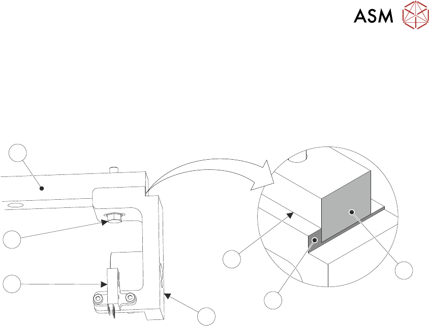
2. Locate the front left magnet support bracket (4) and home sensor (5) attached to the left linear
bearing rail (7).
6
5
4
3
7
1
2
3. Ensure that the datum edge (3) of the support bracket is against the left side of the linear
bearing rail, and that the end faces of the linear bearing rail (1) and the support bracket datum
edge (2) sit flush.
If the datum edge and end faces are positioned as described, then the home sensor is cor-
rectly positioned. Procedure complete.
If the datum edge and end faces are NOT positioned as described, continue at Step 4.
4. Using an 8mm spanner, loosen the M5 hex head bolt (6).
5. Adjust the position of the magnet support bracket (4) till positioned as Step 3.
6. Using an 8mm spanner, tighten the M5 hex head bolt (6).