ASM_MANUAL_TYPHOON_USC_en_100620_online.PDFA - 第36页
3 TYPHOON UNDER STENCIL CLEANER 3.8 ADJUSTMENTS AND SETTINGS 36 STANDALONE MANUAL TYPHOON UNDER STENCIL CLEANER 06/2020 3.8.2 Under Stencil Cleaner Parallelism and Magnet Positions This adjustment ensures that the under …
3 TYPHOON UNDER STENCIL CLEANER
3.8 ADJUSTMENTS AND SETTINGS
STANDALONE MANUAL TYPHOON UNDER STENCIL CLEANER 06/2020 35
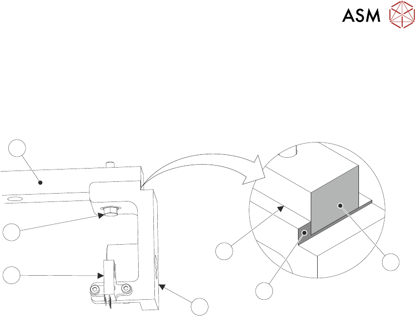
3.8.1 Under Stencil Cleaner Home Position
To check and set the stencil cleaner home position:
1. Open the front printhead cover.
2. Locate the front left magnet support bracket (4) and home sensor (5) attached to the left linear
bearing rail (7).
6
5
4
3
7
1
2
3. Ensure that the datum edge (3) of the support bracket is against the left side of the linear
bearing rail, and that the end faces of the linear bearing rail (1) and the support bracket datum
edge (2) sit flush.
If the datum edge and end faces are positioned as described, then the home sensor is cor-
rectly positioned. Procedure complete.
If the datum edge and end faces are NOT positioned as described, continue at Step 4.
4. Using an 8mm spanner, loosen the M5 hex head bolt (6).
5. Adjust the position of the magnet support bracket (4) till positioned as Step 3.
6. Using an 8mm spanner, tighten the M5 hex head bolt (6).
3 TYPHOON UNDER STENCIL CLEANER
3.8 ADJUSTMENTS AND SETTINGS
36 STANDALONE MANUAL TYPHOON UNDER STENCIL CLEANER 06/2020
3.8.2 Under Stencil Cleaner Parallelism and Magnet Positions
This adjustment ensures that the under stencil cleaner assembly, under stencil cleaner magnets,
and camera beam pickup magnets are parallel to, and positioned to align to the camera beam and
the bracket mounted home magnets.
1. Remove the printer front cover and side safety covers.
NOTE
Engineers performing this procedure should be correctly qualified/adequately trained and
must be aware of the implications of operating the printer when covers have been removed.
2. Open the printhead front cover.
3. Remove the stencil (if fitted).
4. Ensure that the under stencil cleaner is pulled toward the front of the printer.
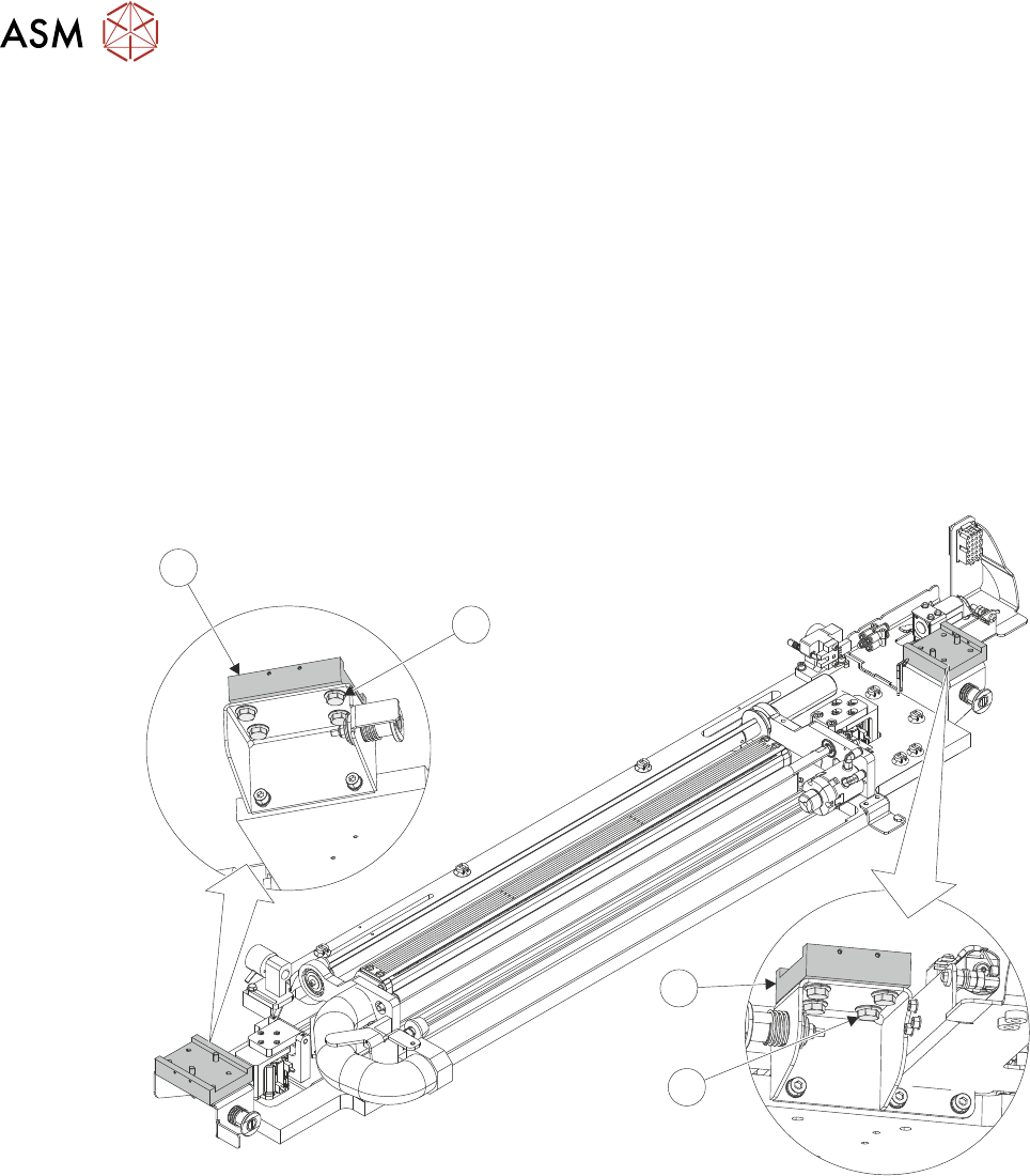
5. Loosen the 4 Durlok screws (1) that attach the left-hand end of the USC assembly to the left
hand linear bearing block (2).
2
1
1
2
6. Repeat Step 5 for the right -hand of the USC assembly.
7. Close the printhead front cover.
8. Switch the mains isolator switch to ON.
9. When prompted by HMI monitor, select Diagnostics.
10. Press System button on printer cover.
11. Use Next or Previous to highlight Screen Cleaner.
12. Select Run Diagnost.
13. Use Next or Previous to highlight Toggle Screen Cleaner Home Clamp.
14. Select Run Diagnost.
Toggle Screen Cleaner Home Clamp to OFF.
15. Open the printhead front cover.
3 TYPHOON UNDER STENCIL CLEANER
3.8 ADJUSTMENTS AND SETTINGS
STANDALONE MANUAL TYPHOON UNDER STENCIL CLEANER 06/2020 37
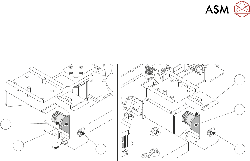
16. Ensure the USC assembly is in the home position, and the USC magnets contact the home
magnets.
17. Loosen and adjust the home magnets M4 retaining screws (5) to align the faces of the mag-
nets (3)/(4) in the X plane, for the left and right magnet assemblies.
3
3
55
4
4
18. Close the printhead front cover.
19. Press System button on printer cover.
20. Use Next or Previous to highlight Toggle Screen Cleaner Home Clamp.
21. Select Run Diagnost.
Toggle Screen Cleaner Home Clamp to ON.
22. Open the printhead front cover.
23. With the magnets holding the USC assembly in place, fully tighten the 8 Durlok screws (4 per
end) to 21Nm using a torque wrench.
24. Close the printhead front cover.
25. Press System button on printer cover.
26. Select Run Diagnost.
Toggle Screen Cleaner Home Clamp to OFF.
27. Open the printhead front cover.
28. Move the USC assembly away from the home position, and then return, ensuring the magnets
engage/align fully and simultaneously fully.
If adjustment is required, loosen the Durlok screws and repeat Steps 14 to 28.
29. Manually move the camera beam forwards to the USC assembly.
The right-hand camera magnet (6) should make contact with the plate magnet catch (9) be-
fore the left-hand camera magnet (7) contacts the board stop mounted pickup bracket (8).
NOTE
Due to the spring (10) on the cleaner attached sensor, the camera beam must be held sta-
tionary as the cleaner is moved to it.