ASM_MANUAL_TYPHOON_USC_en_100620_online.PDFA - 第39页
3 TYPHOON UNDER STENCIL CLEANER 3.8 ADJUSTMENTS AND SETTINGS STANDALONE MANUAL TYPHOON UNDER STENCIL CLEANER 06/2020 39 3.8.3 Under Stencil Cleaner Height To set the under stencil cleaner height, complete the following p…
3 TYPHOON UNDER STENCIL CLEANER
3.8 ADJUSTMENTS AND SETTINGS
38 STANDALONE MANUAL TYPHOON UNDER STENCIL CLEANER 06/2020
9
8
7
6
10
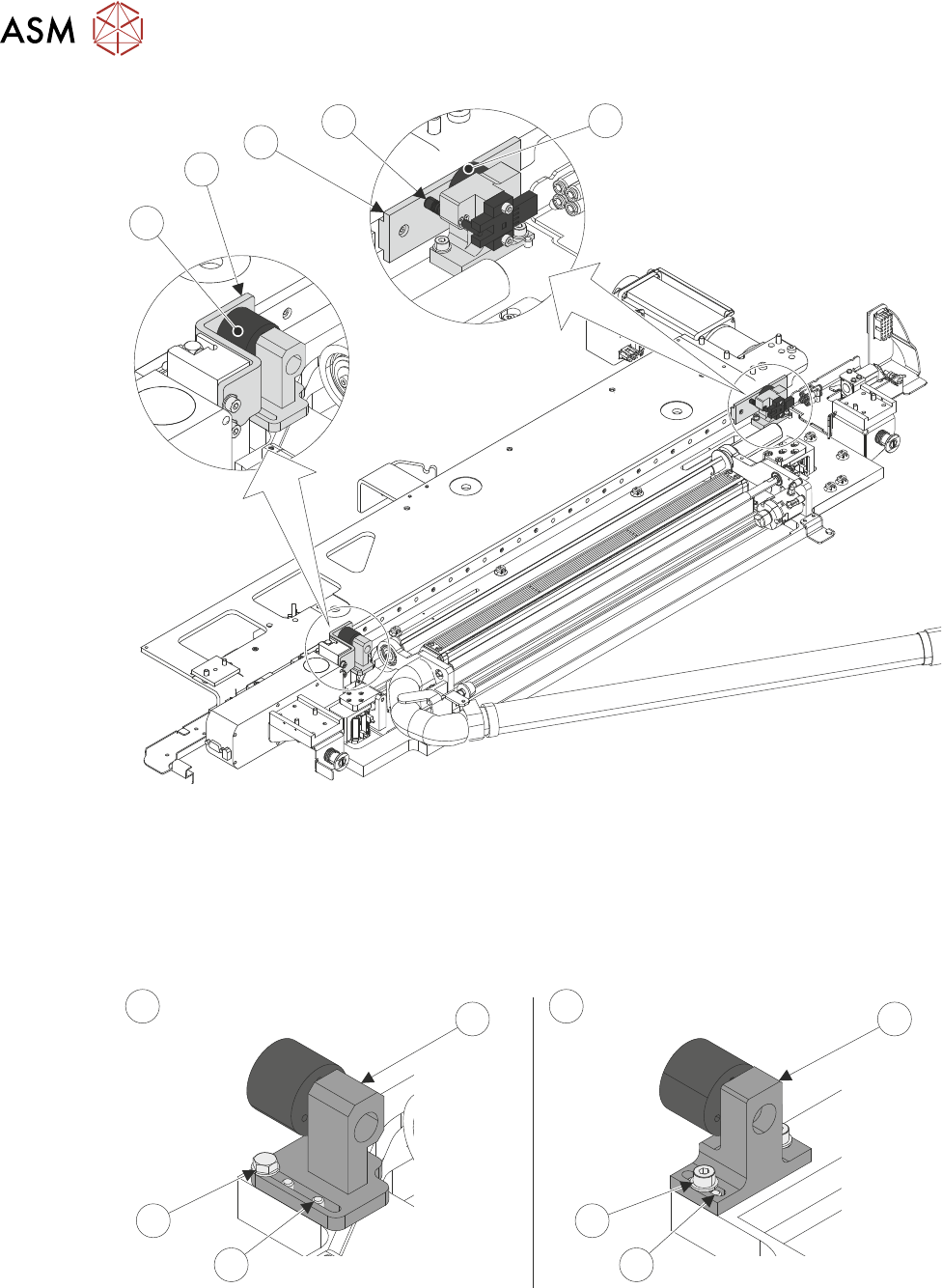
30. The left-hand camera magnet bracket (11)/(14) position needs to be adjusted to make contact
with the magnet catch (7).
Standard Width USC (A): loosen the two bracket securing bolts (13) using a spanner. Re-
position the magnet bracket (11) so the magnet makes contact with the magnet catch.
Long Board (620mm) USC (B): loosen the two bracket securing screws (16). Re-position the
magnet bracket (14) so the magnet makes contact with the magnet catch.
11 14
12
15
13 16
A B
31. Fully lock off the left-hand magnet bracket fasteners (13)/(16).

3 TYPHOON UNDER STENCIL CLEANER
3.8 ADJUSTMENTS AND SETTINGS
STANDALONE MANUAL TYPHOON UNDER STENCIL CLEANER 06/2020 39
3.8.3 Under Stencil Cleaner Height
To set the under stencil cleaner height, complete the following procedure:
NOTE
Prior to starting this procedure, ensure that there is access to the cleaner setting jig kit
(03226762-01).
1. In the machine software, select Setup Product.
2. Select Load Product.
3. Select 265test1.
4. Select Load.
5. Select Back.
6. Check the Board Width parameter:
If Board Width is set to 250.0mm, go to Step 10.
If Board Width is not set to 250.mm, continue at next Step.
7. Select Board Width parameter.
8. Adjust width of board to 250.mm.
9. Select Accept.
10. Select Back.
11. Select Maintenance.
12. Select Diagnostics.
13. Use Next or Previous to highlight Print Carriage.
14. Select Select Module.
15. Use Next or Previous to highlight Drive Carriage To Rear Position.
16. Select Run Diagnost.
17. Select Exit.
18. Use Next or Previous to highlight Rail System.
19. Select Select Module.
20. Use Next or Previous to highlight Drive Rail To Board Width.
21. Select Run Diagnost.
22. Select Exit.
23. Use Next or Previous to highlight Rising Table.
24. Select Select Module.
25. Use Next or Previous to highlight Raise Table To Vision Height.
26. Select Run Diagnost.
27. Open the front printhead cover.
28. At the left hand home magnet, disconnect the home sensor (8SE10).
3 TYPHOON UNDER STENCIL CLEANER
3.8 ADJUSTMENTS AND SETTINGS
40 STANDALONE MANUAL TYPHOON UNDER STENCIL CLEANER 06/2020
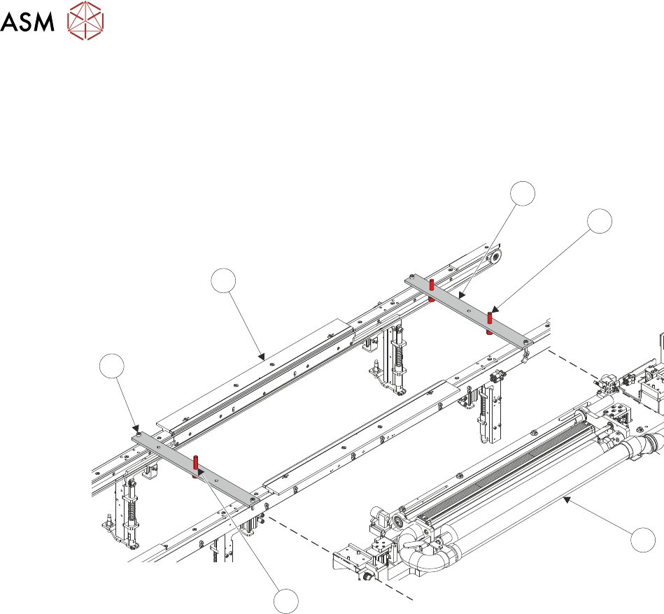
29. Place setting jig rails (1) across the machine's transport rails (6), as close to being inline with
the edges of the USC assembly (3) as possible. The setting rail position screws (5) should
hang just on the outside of the transport rails. The left-hand setting rail has one central lifting
screw (4), the right-hand setting rail has two lifting screws (2).
NOTE
The position of the setting jig rails differs depending on the variant of rail fitted.
1
2
3
4
5
6
30. Remove the plenum chamber (see 3.7.2.1 "Plenum Chamber Removal (Standard
USC)" [}33]).