ASM_MANUAL_TYPHOON_USC_en_100620_online.PDFA - 第44页
3 TYPHOON UNDER STENCIL CLEANER 3.8 ADJUSTMENTS AND SETTINGS 44 STANDALONE MANUAL TYPHOON UNDER STENCIL CLEANER 06/2020 46. Using the setting jig gauge (19) as a GO/NO GO check, check the gap between the chase stencil li…
3 TYPHOON UNDER STENCIL CLEANER
3.8 ADJUSTMENTS AND SETTINGS
STANDALONE MANUAL TYPHOON UNDER STENCIL CLEANER 06/2020 43
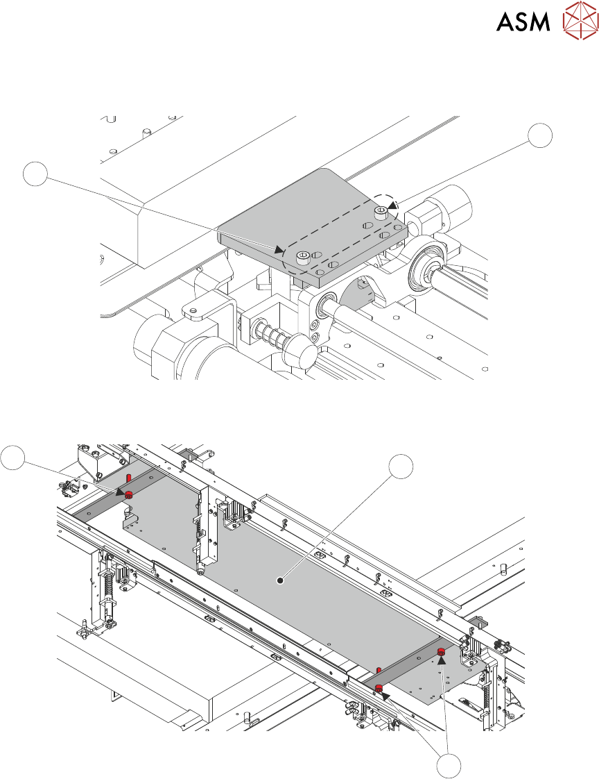
36. Repeat Step 35 for the left-hand setting jig block. Use the inner set of holes (16) for the M5
cap head screws (15).
15
16
37. Move USC assembly (17) over the transport rails, ensuring that the base of the cleaner is
resting on the setting jig rail red adjustment screws (18).
18
17
18
38. Close the printhead cover.
39. Select the System button.
40. Select Exit.
41. Use Next or Previous to highlight Screen Cleaner.
42. Select Select Module.
43. Use Next or Previous to highlight Toggle Dry Wipe Blade.
44. Select Run Diagnost.
45. Open the front printhead cover.
3 TYPHOON UNDER STENCIL CLEANER
3.8 ADJUSTMENTS AND SETTINGS
44 STANDALONE MANUAL TYPHOON UNDER STENCIL CLEANER 06/2020
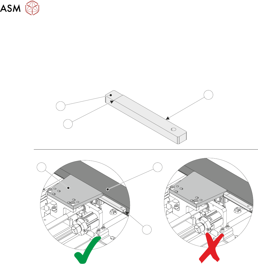
46. Using the setting jig gauge (19) as a GO/NO GO check, check the gap between the chase
stencil lip (22) and the setting jig plates (13) (both sides of each of the plates).
If the lower step (21) of the gauge fits between the underside of the setting plate and the sten-
cil support plate and the upper step edge (20) butts against the edge of the setting plate =
GO. Go to Step 48.
If the lower step (21) of the gauge doesn't fit between the underside of the setting plate (13)
and the stencil support plate (22) OR the lower step (21) of the gauge fits between the under-
side of the setting plate (13) but the upper step edge (20) does not butt against the edge of
the setting plate (13) = NO GO. Continue at next step.
19
19
21
13
22
20
47. Tighten the M8 red nylon cap head screws (18) on the setting jig rails to raise/lower the height
of the USC assembly (as required). Repeat the check at Step 46.
48. At the right hand end of the USC assembly, use a 4mm Allen key to fully tighten end bracket
fasteners (8) loosened at Step 31.
49. At the left hand end of the USC assembly, use a 4mm Allen key to fully tighten end bracket
fasteners (7) loosened at Step 32.
50. Using a 4mm Allen key, remove the four M5 cap head screws fastening the right hand jig set-
ting plate and block to the USC assembly. Remove setting plate and block.
51. Repeat Step 50 for left hand jig setting plate and block.
52. Close the printhead cover.
53. Select the System button.
54. Select Exit.
55. Open the front printhead cover.
56. Install the plenum chamber (see 3.7.2.2 "Plenum Chamber Replacement (Standard
USC)" [}33]).
57. Move the USC assembly back to home position at the front of the machine.
58. Remove the setting jig rails from the machine's transport rails.
3 TYPHOON UNDER STENCIL CLEANER
3.8 ADJUSTMENTS AND SETTINGS
STANDALONE MANUAL TYPHOON UNDER STENCIL CLEANER 06/2020 45
59. At the left hand home magnet, reconnect the home sensor (8SE10).
60. Close the printhead cover.
61. Select the System button.
62. Select Exit.
63. Select Back.
3.8.4 Lift Mechanism Air Flow Controller
Two in-line flow controllers restrict the air flow to the plenum chamber lift actuators to prevent the
USC from hitting the stencil with excessive speed.
The air flow should not need any adjustment unless replaced. Use the following procedure to adjust
the controller (a second person is required for this procedure):
1. Remove machine front panel to gain access to the machine front pneumatic manifold.
NOTE
Some other machine variants have the pneumatic manifold mounted at the rear of the
machine, accessible by removing the rear lower panel.
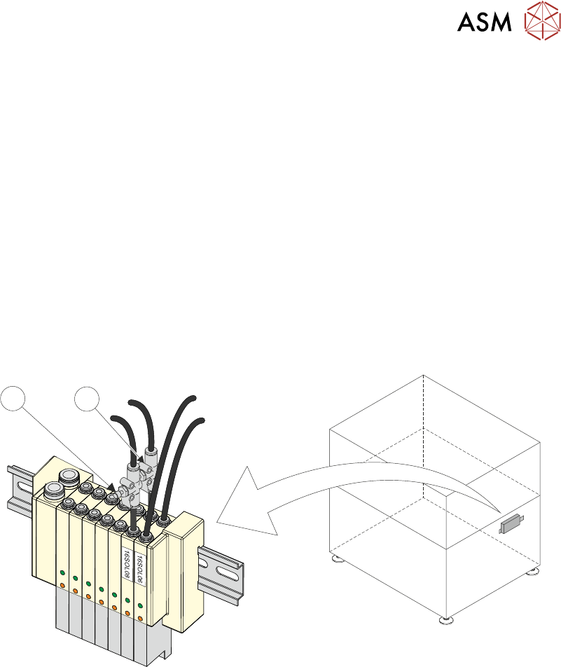
1
2
2. Locate 16SOL08 with air flow controllers (USC Up (1) and USC Down (2)) fitted to the output
ports.
3. Turn the thumbscrews on the air flow controllers fully clockwise to shut off the air supply.
4. Select Load Screen.
5. Open the printhead cover.
6. Fit the calibration stencil into the machine.
7. Close the printhead cover.
8. Press System button.
9. Select Continue.
10. Select Maintenance.
11. Select Diagnostics.
12. Use Next or Previous to highlight Screen Cleaner.
13. Select Select Module.
14. Ensure Toggle Dry Wipe Blade is highlighted.
15. Select Run Diagnost to toggle the lift mechanism up and down.
16. Turn the thumbscrews on the lift mechanism air flow controllers anticlockwise to ensure
smooth, positive operation in both directions (up and down).