00197963-01_AI_Power_Supply_Conversion_SIPLACE_E_en - 第18页
Conversion Installing the Power Conversion Kit 18 Assembly Instructions SIPLACE E 3.3 3 . 3 I n s t a llin g t h e P o w e r C o n v e r s io n K it Installing the Power Conversion Kit The power conversion k it for 3 x 2…
Conversion
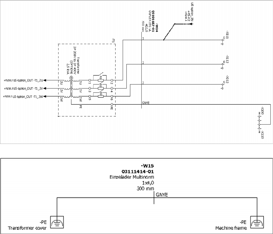
Circuit Diagrams
Assembly Instructions SIPLACE E 17
AC power distribution - US option
Grounding cable for transformer - US option
Conversion
Installing the Power Conversion Kit
18 Assembly Instructions SIPLACE E
3.3
3.3 Installing the Power Conversion Kit
Installing the Power Conversion Kit
The power conversion kit for 3 x 200 – 240 V is installed at location 1 of the SIPLACE E machine.
The main switch and the power supply cable remain the same as they can be used in a 200 V supply
network.
The connections for station computer, LCD screens, and component tables remain unchanged because
they are connected to the placement machine's own supply system.
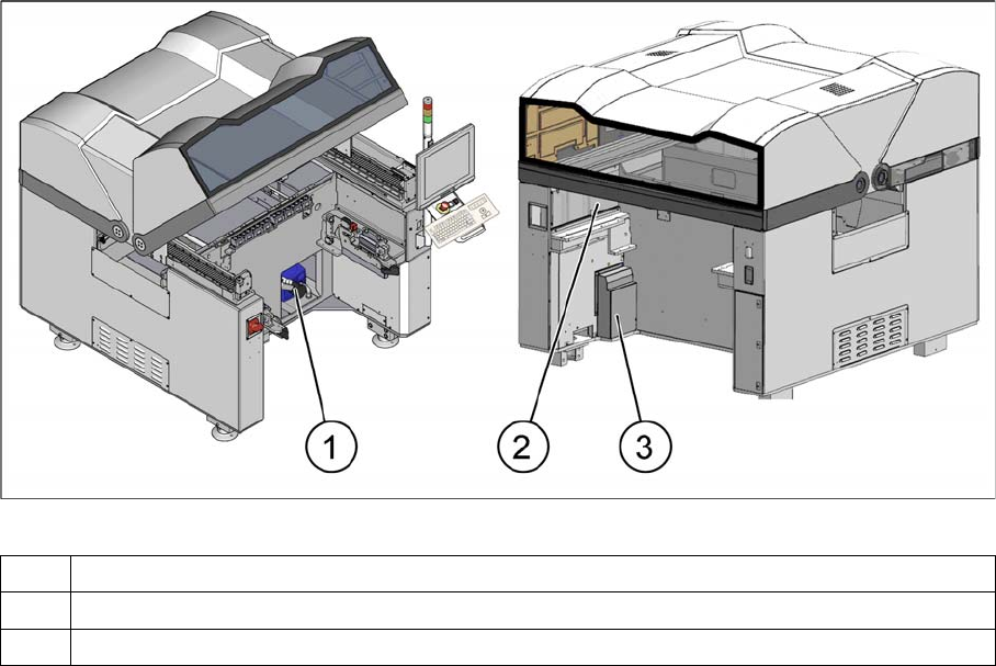
View of location 1 with transformer cover already installed
1 Location of vacuum pump unit
2 Location of vacuum pump control unit and terminal blocks -X111/-X112/-X113
3 Installation location of the transformer behind the cover [03111406-xx]
Conversion
Installing the Power Conversion Kit
Assembly Instructions SIPLACE E 19
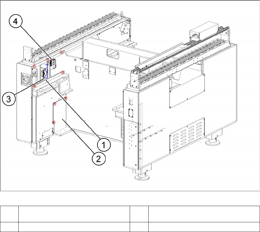
Remove covers
► Remove the cover in front of the vacuum pump control unit (1).
► Remove the standard cover that hides the installation location of the transformer (2).
1 Cover in front of vacuum pump control unit
removed
2 Standard cover [03112972-xx] in front of in
-
stallation location of the transformer
3 PE frame 4 Vacuum pump control unit