00197963-01_AI_Power_Supply_Conversion_SIPLACE_E_en - 第8页
Introduction Preparatory Work... 1.1.5 Safety Instructions on Hazardous Materials 8 Assembly Instructions SIPLACE E 1.2 1 . 2 P r e p a r a t o r y W o r k . . . Preparatory Work... Purpose and Scope Before perfo rming a…

Introduction
1.1.4 Safety Instructions for the Power Supply Safety Instructions
Assembly Instructions SIPLACE E 7
1.1.4
1.1.4 Safety Instructions for the Power Supply
Safety Instructions for the Power Supply
▪ This means that some parts of the system carry potentially lethal voltages - even when switched off
at the main power switch.
▪ Incorrect handling of the placement system can therefore result in fatal injuries, severe injuries or
considerable damage to equipment.
▪ Measurements and maintenance work must always be carried out by appropriately qualified person
-
nel.
▪ Always follow the applicable accident prevention and DIN regulations (particularly DIN EN 60 204,
part 1) or the regulations specific to your country.
▪ Before starting any maintenance work, switch the machine off at the main switch and disconnect it
from the main power supply.
▪ Always secure the machine against unauthorized reactivation. If these instructions are not followed,
you may be able to touch live parts, which could result in fatal or severe injuries.
Maintaining, Installing or Removing Assemblies
► End all placement operations on the machine.
► Shut down the Windows operating system correctly, otherwise problems may occur when restarting
or data may be lost.
► Switch the machine off at the main switch.
► Disconnect the machine from the main power supply.
► Switch off the machine and attach warnings signs to indicate that service work is in progress.
1.1.5
1.1.5 Safety Instructions on Hazardous Materials
Safety Instructions on Hazardous Materials
WARNING
Hazardous Voltages!
The machine is supplied with 3 x 400 V~ (or. 3 x 204 V~ / 3 x 220 V~ / 3 x 230 V~ / 3 x 380 V~
/ 3 x 415 V~) ± 5 %, 50/60 Hz mains voltages.
► Observe the safety instructions in the user manual during all service work!
CAUTION
Observe the safety data sheets
Observe the applicable safety data sheet, when handling hazardous materials (e. g. Loctite
241, ethanol).
Introduction
Preparatory Work... 1.1.5 Safety Instructions on Hazardous Materials
8 Assembly Instructions SIPLACE E
1.2
1.2 Preparatory Work...
Preparatory Work...
Purpose and Scope
Before performing any preventive maintenance work, conversion work or service work, a procedure of
locking and tagging must be followed and warning signs must be attached if not stated otherwise. If it is
not necessary to switch off the machine, it is explicitly mentioned.
The procedure, when followed correctly, eliminates the possibility of an employee being injured.
Description
Whenever it becomes necessary to isolate, control and release energy, the following procedure is to be
followed.
► Notify affected employees.
► Switch off the machine and all additional devices. Carry out all normal stopping procedures:
⇨ Press the STOP button.
⇨ Shut down the station computer.
⇨ Switch the machine off at the main switch.
► Isolate the machine from all its energy sources:
⇨ Shut off the compressed air supply.
⇨ Shut off the main power supply.
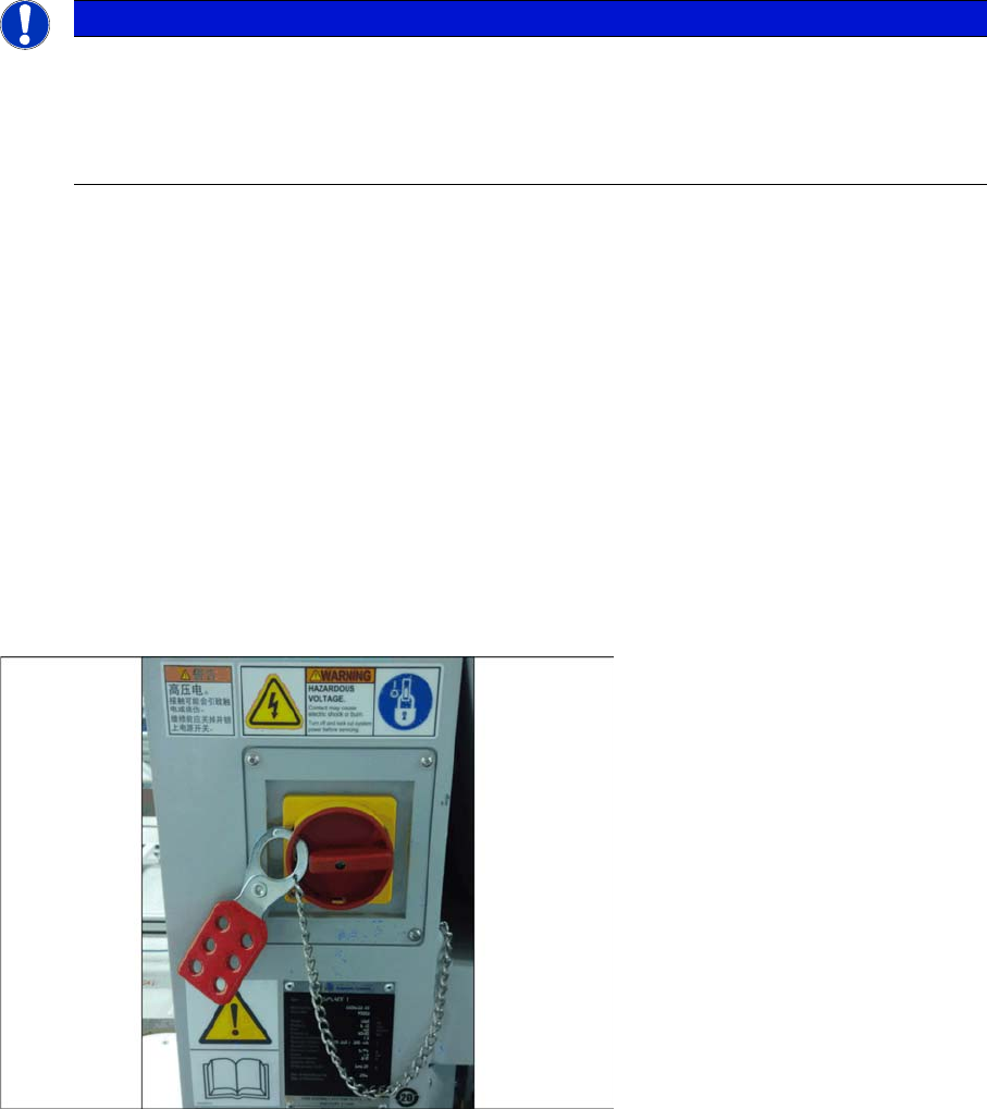
► Lock out the machine.
⇨ Attach a lock wherever possible (e.g. to the main power switch or the motor contactor).
► Alternative: attaching warning signs
If a machine can be locked, it must be. However, there are situations where energy isolating devices
cannot accommodate locks. In these cases, the energy isolating devices must be tagged to warn
employees that the machine is de-energized for servicing. The tag or label must be securely fas
-
tened, it must be placed in a position visible to all and it may only be removed by the person who
attached it.
NOTICE
Additional safety measures
These procedures represent the minimum lock/tag out requirements for the machine during
preventive maintenance work and service work. Any additional safeguards needed to complete
work safely can be specified by facilities supervision, the safety officer, the safety committee
and the health department.
Example
Introduction
1.1.5 Safety Instructions on Hazardous Materials Preparatory Work...
Assembly Instructions SIPLACE E 9
► Release of stored energy:
Stored energy in the compressed air supply or electrical energy in electrolytic capacitors must be
released by appropriate means.
⇨ After switching off the machine, wait until the voltages and the compressed air have discharged,
so that work can be performed without any risk.
► Testing the lock out:
The lock can be easily tested by pressing the START button.
► The following steps must be taken to restore the machine to operation.
► Check the working area. Authorized employees should remove all of their tools and reinstall all safety
features.
► Notify all affected employees.
► Before removing even one lock or tag, inform all workers in the affected area that the machine is
going to be restarted.
► Remove locks/tags
► Every authorized employee must remove his own lock and shut it away.
► Turn the machine on. Make sure that authorized staff check the equipment in operation to ensure
that repairs were performed correctly
Testing
Service personnel may test circuits by energizing them briefly without suspending the Lock Out / Tag
Out Procedure. This may only be done when no other work is being performed by any other person on
the equipment being tested.
It is extremely important that all remote START switches be tagged with the "Do Not Operate" tag to pre
-
vent inadvertent operation of the equipment during these periods.
Responsibilities
▪ It shall be the responsibility of the maintenance and service personnel to make sure this procedure
is adhered to.
▪ It shall be the responsibility of the maintenance and service personnel's immediate supervisor to in
-
struct his personnel on this procedure.
▪ It shall be the responsibility of the Safety Officer with assistance from the Safety Committee, Health
Service Department, and the various managers and vice-presidents to administer the Lock Out / Tag
Out Procedure.