Zusätzliche Start-Stop Taste HF.pdf - 第22页
2 Retrofit Instructions Special design for additional Start-Stop button SIPLACE HF ser ies Special Design 08/2005 Edition 22 2.5 Safety instructions W ARNING The safety instructio ns from the “Operational sa fety” chapte…
Special Design 2 Retrofit Instructions Special design for additional Start-Stop button SIPLACE HF series
08/2005 Edition
21
2 Retrofit Instructions
Special design for additional Start-
Stop button
SIPLACE HF series
2.1 Working principle
The retrofit is intended to allow the covers in the input and output area to be opened once more.2
An additional Start-Stop button is also fitted in the input and output area. 2
2.2 Requirements
Retrofit kit: Start-Stop button for the SIPLACE HF series (item no.: 00166190-xx) 2
2.3 Deliverables
– 2x console panels, left, partly pre-assembled
– 4x spring-mounted lateral thrust pads
– 4x mounting feet
– 2x safety switch actuators
– 1 x push-out tool for Mate-N-Lok connectors
– 1 x retrofit instructions for additional Start-Stop button (item no.: 00194706-xx)
2.4 Tools required
– Set of hexagon socket spanners
–Hammer
– Pliers
– Push-out tool for Mate-N-Lok connectors (supplied as standard)

2 Retrofit Instructions Special design for additional Start-Stop button SIPLACE HF series Special Design
08/2005 Edition
22
2.5 Safety instructions
WARNING
The safety instructions from the “Operational safety” chapter of the user manual and servicing in-
structions take precedence over these instructions. 2
The SIPLACE placement machines are supplied with mains voltage.
Consequently parts of these systems carry dangerous voltages! This voltage is present at certain
modules inside the machine base, even when the machine is switched off at the main power
switch.
Incorrect handling of the placement machine or touching live parts of the machine can result in
death or severe injury, and considerable damage to equipment.
BEFORE starting any work, shut down the operating system correctly, then switch the machine
OFF at the main power switch and disconnect from the main power supply. In addition, the com-
pressed air supply must be switched off at the compressed air unit's main valve in the machine
base and vented by actuating the needle valve on the compressed air unit.
There is DANGER for heart pacemaker wearers in the vicinity of the linear motors, as described
in detail in the "Special safety instructions for working in the vicinity of strong magnetic fields"
section of the user manual and service manual.
Always follow the accident prevention regulations, DIN or other standards and special safety
rules applicable in your country.
Pay attention to the information concerning residual voltages in the Operational Safety chapter.
Follow the ESD regulations as described in the operational safety section of the operating
instructions.
During the retrofit, always secure the machine to prevent access by other people and to prevent
it being switched on again. The procedure is described in the “Locking the machine…” section of
the user manual.
Working with the SITEST program further increases the risk of accident.
The SITEST program must only be used by authorized and trained personnel.
2
2.5.1 Definitions
2
Please note 2
2
2
Special Design 2 Retrofit Instructions Special design for additional Start-Stop button SIPLACE HF series
08/2005 Edition
23
2.6 Installation
: Switch the placement system off at the main switch and disconnect from the main power sup-
ply.
2
Installation is shown on the output belt by way of example. Installation on the input belt is exactly
the same. 2
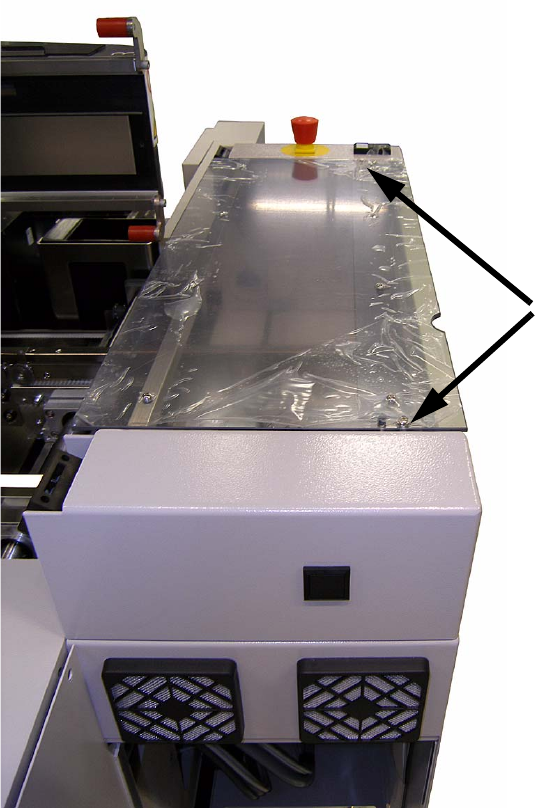
: Remove the cover from the output belt by removing the two screws on the top of the cover.
2
2
2
2
Screws on the cover hood