S27HM Circuit Diagrams.pdf - 第105页
3 - 16 0035664 3-010 301LD3 Circui t diagr am, ter minal pane l voltag es appr ox. up to ser ial no . 224 ( sh. 1 of 2) 1. 1. 17.10.2001 25.11.2000 Tut h Tut h 17.10.2001 Tut h SMD Placement System Siplace S-27 HM Circui…
3 - 15
00356395-040201LD3 Power supply, circuit diagram, option for Japan
approx. up to serial no. 259 (sh. 2 of 2)
1.
4.
21.08.2001
26.06.2001
Tuth
Tuth 26.06.2001
Tuth
Siplace S27 HM SMD Placement SystemPower supply circuit diagram
Option for Japan
approx. up to serial no. 259
00356395-040201LD3
08.02.2001 Tuth
2.
SIEMENS
L&A EA
Status Modified Date Name Standard Orig. Repl.f. Repl. by
Document status
Product status
Function status Date
Author
Check.
Sheet
Sh.
W
e
i
t
e
r
g
a
b
e
s
o
w
i
e
V
e
r
v
i
e
l
f
ä
l
t
i
g
u
n
g
d
i
e
s
e
r
U
n
t
e
r
l
a
g
e
,
V
e
r
-
w
e
r
t
u
n
g
u
n
d
M
i
t
t
e
i
l
u
n
g
i
h
r
e
s
I
n
h
a
l
t
s
n
i
c
h
t
g
e
s
t
a
t
t
e
t
,
s
o
w
e
i
t
n
i
c
h
t
a
u
s
d
r
ü
c
k
l
i
c
h
z
u
g
e
s
t
a
n
d
e
n
.
Z
u
w
i
d
e
r
h
a
n
d
l
u
n
g
e
n
v
e
r
-
p
f
l
i
c
h
t
e
n
z
u
S
c
h
a
d
e
n
e
r
s
a
t
z
.
A
l
l
e
R
e
c
h
t
e
v
o
r
b
e
h
a
l
t
e
n
,
i
n
s
b
e
s
o
n
d
e
r
e
f
ü
r
d
e
n
F
a
l
l
d
e
r
P
a
t
e
n
t
e
r
t
e
i
l
u
n
g
o
d
e
r
G
M
-
E
i
n
t
r
a
g
u
n
g
P
r
o
p
r
i
e
t
a
r
y
d
a
t
e
,
c
o
m
p
a
n
y
c
o
n
f
i
d
e
n
t
i
a
l
.
A
l
l
r
i
g
h
t
s
r
e
s
e
r
v
d
.
C
o
n
f
i
e
a
t
i
t
r
e
d
e
s
e
c
r
e
t
d
´
e
n
t
r
e
p
r
i
s
e
.
T
o
u
s
d
r
o
i
t
s
r
e
s
e
r
v
e
s
.
C
o
m
u
n
i
c
a
d
o
c
o
m
o
s
e
g
r
e
d
o
e
m
p
r
e
s
a
r
i
a
l
.
R
e
s
e
r
v
a
d
o
s
t
o
d
o
s
o
s
d
i
r
e
i
l
o
s
.
C
o
n
f
i
a
d
o
c
o
m
o
s
e
c
r
e
t
e
i
n
d
u
s
t
r
i
a
l
.
N
o
s
r
e
s
e
r
v
a
m
o
s
t
o
d
o
s
l
o
s
d
e
r
e
c
h
o
s
.
A
B
C
D
E
F
1 2 3 4 5 6 7 8
1
2 3 4 5 6 7 8
A
B
C
D
E
F
2
2
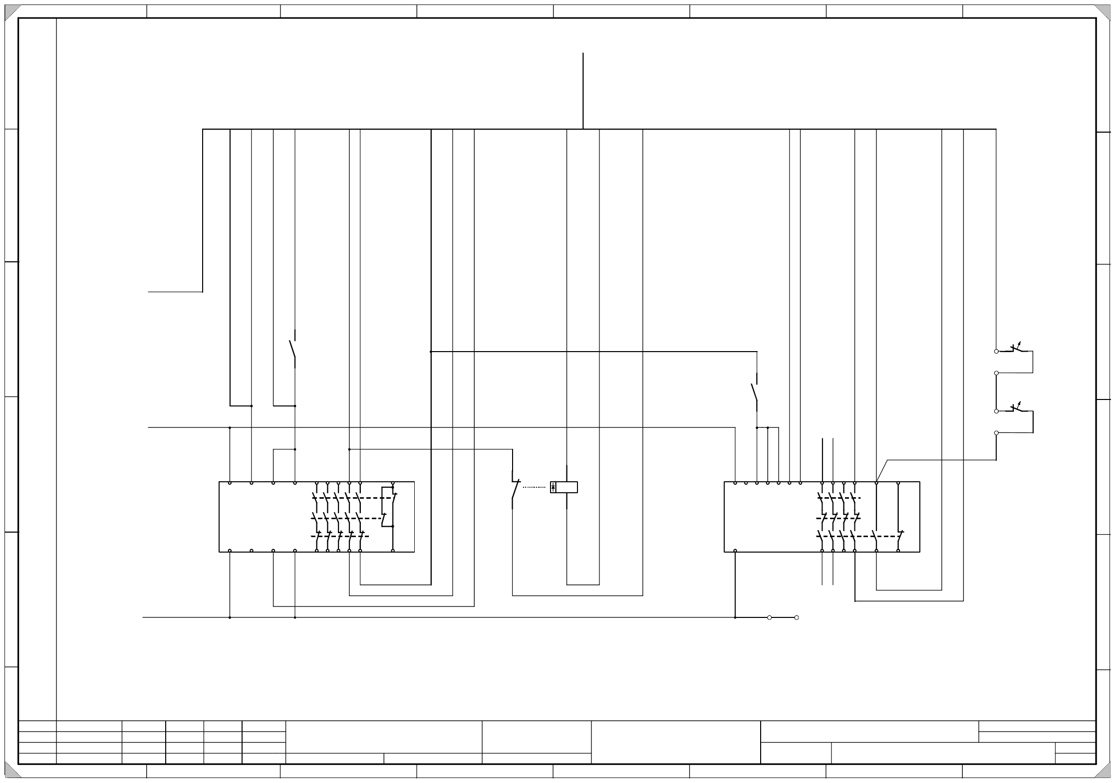
13 23 33 43 53
14 24 34 44 54
65
66
A1 X1 X3 X5
A2 X2 X4 X6
3TK2805
13 23 33 43
57
14 24 34 44 58
65
66
A1 X2 X4 X6
A2 X2
X1 X3 X5
3TK2804
A1(+)
A2(-)
21
22
K3
13
14
K3
43
44
K3
g
y
w
h
b
r
g
n
b
l
w
h
/
g
n
b
k
v
i
b
r
/
g
n
y
e
w
h
/
g
y
g
y
/
b
r
p
k
/
b
r
g
y
/
p
k
r
d
/
b
l
w
h
/
y
e
y
e
/
b
r
S
h
e
e
t
1
7
/
E
Sheet 1 7/E
r
d
p
k
0
0
3
2
1
1
1
3
-
x
x
MP1
T
o
e
x
t
e
r
n
a
l
e
m
e
r
g
.
-
s
t
o
p
c
i
r
c
u
i
t
2
4
V
A
C
2
4
V
A
C
T
o
O
n
b
u
t
t
o
n
F
r
o
m
e
m
e
r
g
.
-
s
t
o
p
c
i
r
c
u
i
t
2
4
V
D
C
F
r
o
m
e
m
e
r
g
.
-
s
t
o
p
c
i
r
c
u
i
t
T
o
k
e
y
s
w
i
t
c
h
T
o
s
i
g
n
a
l
i
n
g
c
i
r
c
u
i
t
,
C
o
n
t
r
o
l
O
n
v
o
m
T
a
s
t
e
E
i
n
F
r
o
m
S
t
a
r
t
b
u
t
t
o
n
T
o
s
i
g
n
a
l
i
n
g
c
i
r
c
u
i
t
,
s
o
f
t
w
a
r
e
r
e
l
e
a
s
e
S
o
f
t
w
a
r
e
r
e
l
e
a
s
e
S
o
f
t
w
a
r
e
r
e
l
e
a
s
e
T
o
S
t
a
r
t
b
u
t
t
o
n
F
r
o
m
S
t
a
r
t
b
u
t
t
o
n
5
0
V
D
C
r
e
l
e
a
s
e
+
2
4
V
D
C
I
n
p
u
t
s
i
g
n
a
l
i
n
g
c
i
r
c
u
i
t
5
0
V
D
C
r
e
l
e
a
s
e
To sheet 1
F10:2 24V AC
To sheet 1
GND
To sheet 1
F7:2 24V AC
AWG 16bk
AWG 16bk
K1 K2
M
1
2
T1
1
2
T2
w
h
/
p
k
bk 0.75
T
1
a
n
d
T
2
t
e
m
p
e
r
a
t
u
r
e
m
o
n
i
t
o
r
i
n
g
Temperature switch
3 - 16
00356643-010301LD3 Circuit diagram, terminal panel voltages
approx. up to serial no. 224 (sh. 1 of 2)
1.
1.
17.10.2001
25.11.2000
Tuth
Tuth 17.10.2001
Tuth
SMD Placement System Siplace S-27 HM
Circuit diagram, terminal panel voltages
approx. up to serial no. 224
00356643-010301LD3
25.11.2000 Tuth
3.
2
SIEMENS
L&A EA
Status Modified Date Name
Standard
Orig. Repl. f. Repl. by
Document status
Product status
Function status Date
Author
Checked
Sheet
Sh.
W
e
i
t
e
r
g
a
b
e
s
o
w
i
e
V
e
r
v
i
e
l
f
ä
l
t
i
g
u
n
g
d
i
e
s
e
r
U
n
t
e
r
l
a
g
e
,
V
e
r
-
w
e
r
t
u
n
g
u
n
d
M
i
t
t
e
i
l
u
n
g
i
h
r
e
s
I
n
h
a
l
t
s
n
i
c
h
t
g
e
s
t
a
t
t
e
t
,
s
o
w
e
i
t
n
i
c
h
t
a
u
s
d
r
ü
c
k
l
i
c
h
z
u
g
e
s
t
a
n
d
e
n
.
Z
u
w
i
d
e
r
h
a
n
d
l
u
n
g
e
n
v
e
r
-
p
f
l
i
c
h
t
e
n
z
u
S
c
h
a
d
e
n
e
r
s
a
t
z
.
A
l
l
e
R
e
c
h
t
e
v
o
r
b
e
h
a
l
t
e
n
,
i
n
s
b
e
s
o
n
d
e
r
e
f
ü
r
d
e
n
F
a
l
l
d
e
r
P
a
t
e
n
t
e
r
t
e
i
l
u
n
g
o
d
e
r
G
M
-
E
i
n
t
r
a
g
u
n
g
P
r
o
p
r
i
e
t
a
r
y
d
a
t
e
,
c
o
m
p
a
n
y
c
o
n
f
i
d
e
n
t
i
a
l
.
A
l
l
r
i
g
h
t
s
r
e
s
e
r
v
d
.
C
o
n
f
i
e
a
t
i
t
r
e
d
e
s
e
c
r
e
t
d
´
e
n
t
r
e
p
r
i
s
e
.
T
o
u
s
d
r
o
i
t
s
r
e
s
e
r
v
e
s
.
C
o
m
u
n
i
c
a
d
o
c
o
m
o
s
e
g
r
e
d
o
e
m
p
r
e
s
a
r
i
a
l
.
R
e
s
e
r
v
a
d
o
s
t
o
d
o
s
o
s
d
i
r
e
i
l
o
s
.
C
o
n
f
i
a
d
o
c
o
m
o
s
e
c
r
e
t
e
i
n
d
u
s
t
r
i
a
l
.
N
o
s
r
e
s
e
r
v
a
m
o
s
t
o
d
o
s
l
o
s
d
e
r
e
c
h
o
s
.
A
B
C
D
E
F
1 2 3 4 5 6 7 8
1
2 3 4 5 6 7 8
A
B
C
D
E
F
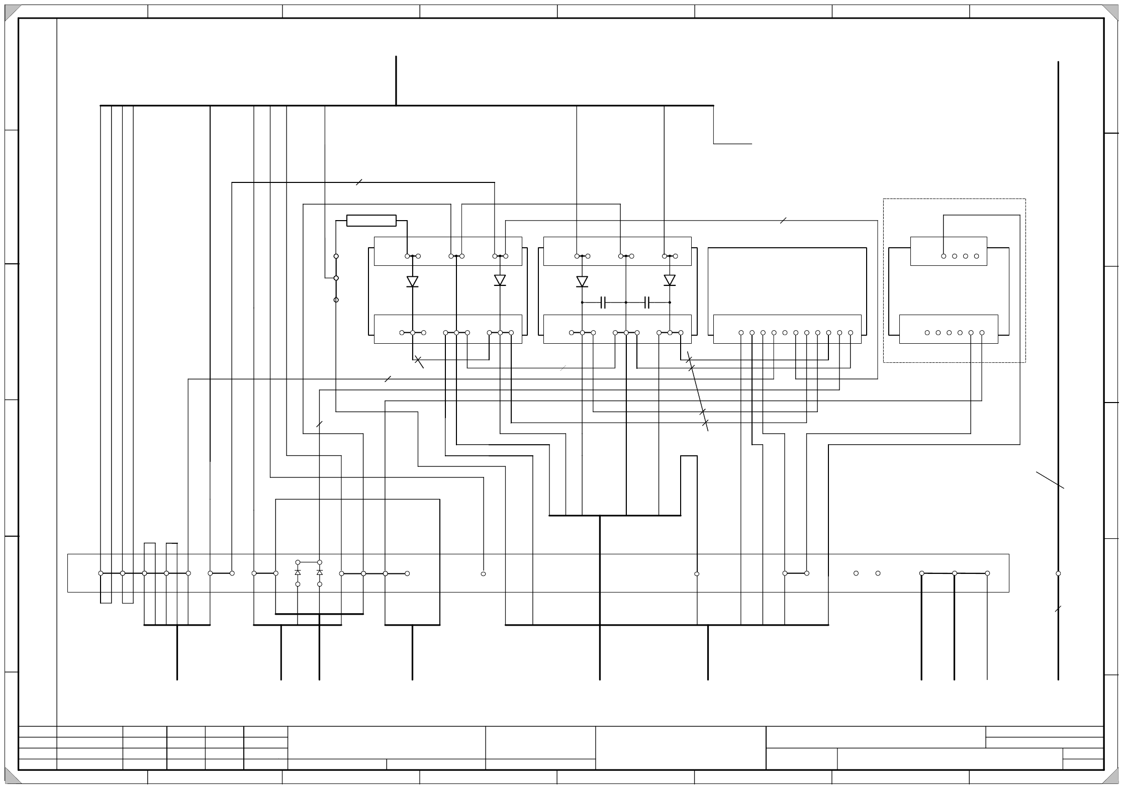
1
X1
1234567891011
A5
(re)
X2
123 456 789
X1
12 34 56
++
A4
(rd)
X2
123 456 789
X1
12 34 56
A3
(rc)
X6
123456
X7
1234
A1
(ra)
G
N
D
+
2
4
V
+
5
0
V
4R7 / 5W
78
54
2 3
To
power supply
unit
To
servo unit
To
tape cutter 1
To
tape cutter 2
To
pneumatic unit
To
servo unit
To
terminal panel
I/O distributor
1
L
+
1
L
+
1
L
+
1
L
+
3
L
+
2
L
+
2
L
+
1
2
4
1
1
5
3
8
6
4
L
+
5
L
+
7
1
0
7
L
+
y
e
g
y
p
k
g
n
4
2
4
5
1
3
6
w
h
b
n
b
n
b
n
g
n
g
n
8
g
y
g
y
b
n
1
L
+
1
L
+
1
L
+
1
L
+
3
L
+
2
L
+
2
L
+
2
L
-
1
2
4
1
1
5
3
b
k
g
y
y
e
b
k
b
l
b
k
9
6
L
+
b
l
b
k
b
l
b
k
b
l
b
k
w
h
w
h
b
n
b
k
2L+
6L+
2L+
2L-
b
n
2
w
h
w
h
5
1
g
y
w
h
w
h
w
h
b
k
b
k
w
h
w
h
w
h
g
n
g
n
y
e
3
6
w
h
w
h
w
h
w
h
1
2
3
4
6
5
b
n
y
e
g
y
b
l
0
0
3
0
0
1
6
4
-
x
x
0
0
3
4
4
7
7
3
-
x
x
0
0
3
1
3
4
0
0
-
x
x
0
0
3
1
3
4
0
0
-
x
x
0
0
3
0
0
1
6
3
-
x
x
0
0
3
5
6
7
3
3
-
x
x
1 mm
2
1 mm
2
1 mm
2
1.5 mm
2
1 mm
2
1 mm
2
1 mm
2
b
l
X
2
0
7
0
0
3
2
4
3
5
9
-
x
x
0
0
3
2
4
3
5
8
-
x
x
10 mm
2
10 mm
2
9
To
power supply
unit
2
L
-
6
A2
10
1
1
To
servo unit
1 mm
2
1 mm
2
1 mm
2
0
0
3
0
6
8
8
0
-
x
x
Multi-color camera option
A2 - MPE
g
n
y
e
6
q
m
m
(
c
o
n
t
r
o
l
u
n
i
t
)
g
n
y
e
6
q
m
m
(
s
e
r
v
o
u
n
i
t
)
0
0
3
4
4
2
1
9
-
x
x
0
0
3
2
1
5
8
2
-
x
x
g
n
y
e
X206:PE
R1
0
0
3
4
9
9
2
2
-
x
x
g
n
y
e
t
o
m
o
n
i
t
o
r
3 - 17
00356643-010301LD3 Circuit diagram, terminal panel voltages
approx. up to serial no. 224 (sh. 2 of 2)
1.
1.
17.10.2001
25.11.2000
Tuth
Tuth 17.10.2001
Tuth
SMD Placement System Siplace S-27 HM
Circuit diagram, terminal panel voltages
approx. up to serial no. 224
00356643-010301LD3
25.11.2000 Tuth
3.
2
SIEMENS
L&A EA
Status Modified Date Name
Standard
Orig. Repl. f. Repl. by
Document status
Product status
Function status Date
Author
Checked
Sheet
Sh.
W
e
i
t
e
r
g
a
b
e
s
o
w
i
e
V
e
r
v
i
e
l
f
ä
l
t
i
g
u
n
g
d
i
e
s
e
r
U
n
t
e
r
l
a
g
e
,
V
e
r
-
w
e
r
t
u
n
g
u
n
d
M
i
t
t
e
i
l
u
n
g
i
h
r
e
s
I
n
h
a
l
t
s
n
i
c
h
t
g
e
s
t
a
t
t
e
t
,
s
o
w
e
i
t
n
i
c
h
t
a
u
s
d
r
ü
c
k
l
i
c
h
z
u
g
e
s
t
a
n
d
e
n
.
Z
u
w
i
d
e
r
h
a
n
d
l
u
n
g
e
n
v
e
r
-
p
f
l
i
c
h
t
e
n
z
u
S
c
h
a
d
e
n
e
r
s
a
t
z
.
A
l
l
e
R
e
c
h
t
e
v
o
r
b
e
h
a
l
t
e
n
,
i
n
s
b
e
s
o
n
d
e
r
e
f
ü
r
d
e
n
F
a
l
l
d
e
r
P
a
t
e
n
t
e
r
t
e
i
l
u
n
g
o
d
e
r
G
M
-
E
i
n
t
r
a
g
u
n
g
P
r
o
p
r
i
e
t
a
r
y
d
a
t
e
,
c
o
m
p
a
n
y
c
o
n
f
i
d
e
n
t
i
a
l
.
A
l
l
r
i
g
h
t
s
r
e
s
e
r
v
d
.
C
o
n
f
i
e
a
t
i
t
r
e
d
e
s
e
c
r
e
t
d
´
e
n
t
r
e
p
r
i
s
e
.
T
o
u
s
d
r
o
i
t
s
r
e
s
e
r
v
e
s
.
C
o
m
u
n
i
c
a
d
o
c
o
m
o
s
e
g
r
e
d
o
e
m
p
r
e
s
a
r
i
a
l
.
R
e
s
e
r
v
a
d
o
s
t
o
d
o
s
o
s
d
i
r
e
i
l
o
s
.
C
o
n
f
i
a
d
o
c
o
m
o
s
e
c
r
e
t
e
i
n
d
u
s
t
r
i
a
l
.
N
o
s
r
e
s
e
r
v
a
m
o
s
t
o
d
o
s
l
o
s
d
e
r
e
c
h
o
s
.
A
B
C
D
E
F
1 2 3 4 5 6 7 8
1
2 3 4 5 6 7 8
A
B
C
D
E
F
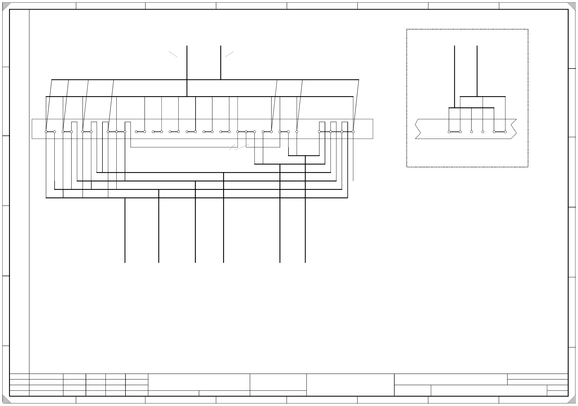
7-8 230V (Station computer)
10-11 150V (Control unit)
Machine connected to 3x208/120V (USA)
L1-L2-L3,N 3x208/120V (Component tables and WPC)
7-8 230V (Station computer)
10-11 150V (Control unit)
At the terminals X206 the following voltages are available:
Machine connected to 3x400/230V
L1-L2-L3 / N 3x400/230V (Component tables and WPC)
This document displays the standard terminal assignment for European electric network
3x400/230V and USA network 3x208/120V with neutral conductor.
956 10 11
X
2
0
6
From
power supply unit
To
WPC 1
To
WPC 2
To
CO table 1
To
CO table 2
To
stations
computer
To
main power supply
control unit
789
X206
PE
To
UPS
From
UPS
0
0
3
4
4
5
3
9
-
x
x
0
0
3
4
4
5
4
0
-
x
x
b
l
b
l
b
n
b
n
y
e
g
n
y
e
g
n
UPS option
2
PE
8
g
n
y
e
1
3
9
1
0
5
6
3
4
1
2
b
k
0
0
3
2
2
1
0
9
-
x
x
0
0
3
2
2
1
1
0
-
x
x
0
0
3
2
2
0
6
7
-
x
x
0
0
3
2
2
0
6
8
-
x
x
0
0
3
2
1
4
9
6
-
x
x
0
0
3
4
4
2
1
2
-
x
x
b
k
b
n
b
n
b
k
b
k
b
l
b
l
2
1
b
l
b
r
g
n
y
e
g
n
y
e
g
n
y
e
g
n
y
e
g
n
y
e
g
n
y
e
432
8
1
7
N
L3L2L1
1
1
1
2
1
4
0
0
3
5
6
5
4
0
-
x
x
b
l
b
l
7
b
n
b
n
Notes for Japan network
When the machine is operated in an network without neutral conductor (3x200V in Japan)
make sure to reconnect the following cables at terminal block X206:
g
n
y
e
(
0
0
3
5
6
7
3
3
-
x
x
)
After checking the voltages at terminal X206 cover them
with the voltage warning labels except for N and PE!
Please note:
(
1
)
(
1
)
(
2
)
(
2
)
(
1
)
(
3
)
(
3
)
(
1
)
(
4
)
(
4
)
(
2
)
(
2
)
g
n
y
e
(
5
)
(
4
)
(
6
)
(
3
)
(
2
)
(
1
)
0
0
3
5
7
8
9
8
-
x
x
Power supply units
from 00336812-03
with neutral conductor
Power supply units
from 00356395-xx
without neutral conductor
(Japan network)
(power supply in 00356395 diagram)
bl 2.5qmm
When using power supply unit mat. no. 00356395-xx (Japan option)
you must remove
the 2.5 mm² jumpers between X206-N and X206-7
and between X206-7 and X206-10. Otherwise the jumpers will cause
a short circuit.
WARNING !!!
7 and 10 jumpered with N
Cable 00322109-xx: wire bk from L1 to 1; wire bn from L2 to 2; wire bk from L3 to 3; wire bl from N to 4
Cable 00322110-xx: wire bk from L1 to 1; wire bn1 from L2 to 2; wire bk from L3 to 3; wire bl from N to 4
Machine connected to 3x200V (Japan)
Cable 00322067-xx: wire bn from L2 to 5; wire bl from N to 6;
Cable 00322068-xx: wire bn from L3 to 5; wire bl from N to 6;
At the terminals X206 the following voltages are available:
1-2-3 / 4 3x400/230V ( WPC)
5-6 230V ( Component tables)
7-8 230V (Station computer)
10-11 150V (Control unit)
When using a UPS connect the
cables to and from the UPS in
the following way:
Remove jumper X206 8-9!