S27HM Circuit Diagrams.pdf - 第108页
3 - 19 0037522 1-010 102LD3 Circuit diagram, termin al blo ck voltages appr ox. f rom se rial no . 225 (s h. 2 of 2) 4567 8 1 2 34567 8 A B C D E F 9 5 6 10 11 X206 From power suppl y unit To WPC 1 A B C D E F 12 3 To WP…
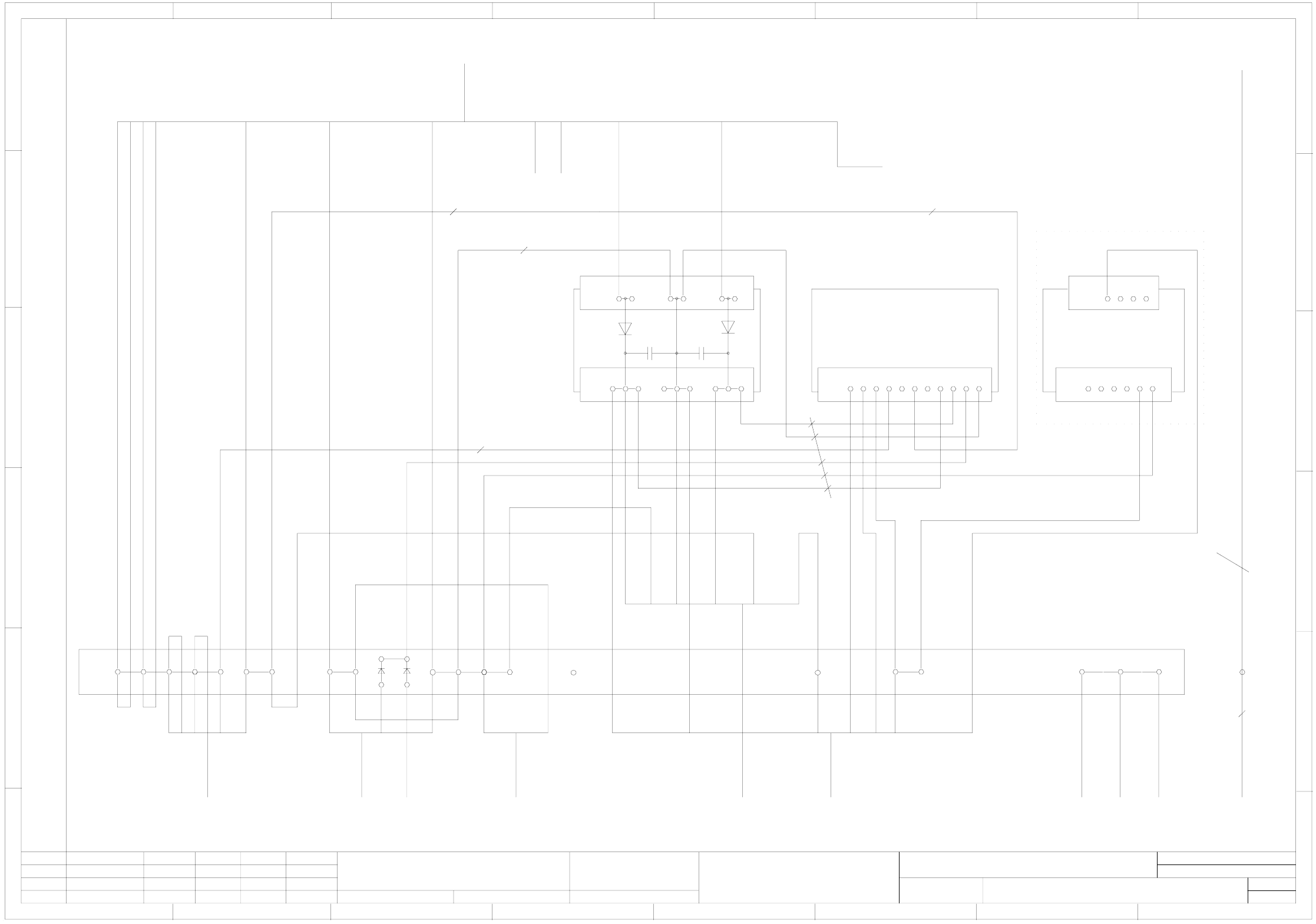
3 - 18
00375221-010102LD3 Circuit diagram, terminal block voltages
approx. from serial no. 225 (sh. 1 of 2)
4567 8
1234567 8
A
B
C
D
E
F
1
X1
1234567891011
A5
(re)
Shrink individually
A
B
C
D
E
F
12 3
X2
123 456 789
X1
12 34 56
++
A4
(rd)
X6
123456
X7
1234
A1
(ra)
GND
+24V
+50V
78
54
23
To power supply unit
To servo unit To tape cutter 1 To tape cutter 2 To pneumatic unit
To servo unit To terminal block
I/O distributor
1L+
1L+
1L+
1L+
3L+
2L+
1
2
4
11
5
3
8
6
4L+
5L+
7
10
7L+
ye
gy
pk
gn 4
2
4
5
1
3
6
wh
bn
bn
bn
gn
gn
8
gy
gy
bn
1L+
1L+
1L+
1L+
3L+
2L+
2L+
2L-
1
2
4
11
5
3
bk
gy
bk
bubk
9
6L+
bubk
bubk
bubk
wh
wh
bn
bk
2L+
2L+
2L-
bn
2
wh
5
1
gy
wh
wh
wh
wh
wh
1
2
3
4
6
5
bn
ye
gy
bu
00300164-xx
00344773-xx
00313400-xx
00313400-xx
00300163-xx
00356733-xx
1 mm²
1 mm²
1 mm²
1.5 mm² bk
bu
X207
00324359-xx
00324358-xx
10 mm²
To power supply unit
2L-
6
To servo unit
1 mm²
1 mm²1 mm²
00306880-xx
Option Multi-color camera
A2 - M
PE
gnye 6mm² (control unit)
gnye 6mm² (servo unit)
00344219-xx
00321582-xx
gnye
X206:PE
00349922-xx
gnye to monitor
bn
1 mm² wh
1L+
3
besondere für den Fall der Patenterteilung oder GM-Eintragung
pflichten zu Schadenersatz. Alle Rechte vorbehalten, ins
nicht ausdrücklich zugestanden. Zuwiderhandlungen ver-
wertung und Mitteilung ihres Inhalts nicht gestattet, soweit
Weitergabe sowie Vervielfältigung dieser Unterlage,Ver-
Confiado como secrete industrial. Nos reservamos todos los derechos.
Comunicado como segredo empresarial. Reservados todos os direilos.
Confie a titre de secret d´entreprise. Tous droits reserves.
Proprietary data, company confidential. All rights reserved.
L&A
SIEMENS
Date
Author
Check.
Stand.Status
1 .
2 .
1 .
NameDateModified
Function status
Product status
Document status
25.11.2003
17.02.2004
25.11.2003
Tuth
Tuth
Tuth
Orig.
L&A EA1 R&D
17.02.2004
Tuth
Repl. byRepl. f.
00375221-010102LD3
Circuit diagram: terminal block voltages
SIPLACE S-27 HM
2
Sheet
Sh.
1
10 mm²
approx. from serial no. 225
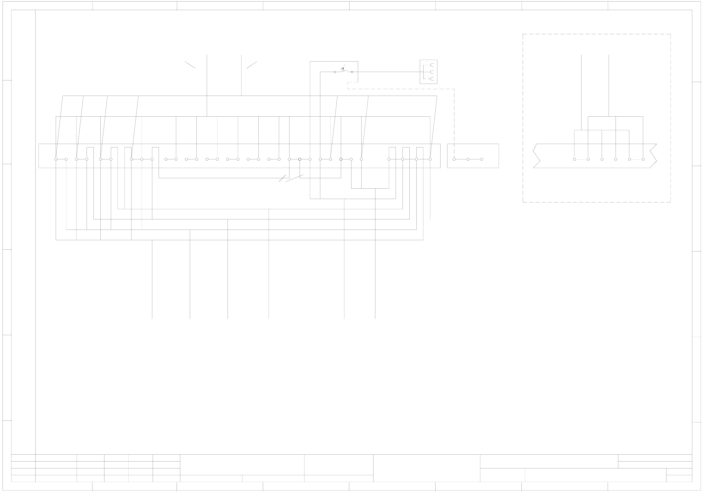
3 - 19
00375221-010102LD3 Circuit diagram, terminal block voltages
approx. from serial no. 225 (sh. 2 of 2)
4567 8
1234567 8
A
B
C
D
E
F
95 6 10 11
X206
From power supply unit
To WPC 1
A
B
C
D
E
F
12 3
To WPC 2 To CO table 1 To CO table 2
To station computer To power supply unit
Control unit
789
X206
PE
To UPSFrom UPS
00344539-xx
00344540-xx
When using a UPS, please connect the cable to and from the UPS in the following way!
Remove jumper X206 8-9!
bu
bu
bn
bn
yegn
yegn
UPS option
PE
8
gnye
13
9
10
5
6
3
4
1
2
bk
00322109-xx
00322110-xx
00322067-xx
00322068-xx
00321496-xx
00344212-xx
bk
bn
bn
bk
bk
bu
bu
2
1
bu
bn
gnye
gnye
gnye
gnye
gnye
gnye
432
8
1
7
N
L3L2L1
11
12
14
00356540-xx
bu
bu
7
bn
bn
Notes for Japan network
This document displays the standard terminal assignment for European electric network 3x400/230V and USA network 3x208/120V with neutral conductor.
At the terminals X206 the following voltages are available:
Machine connected to 3x400/230V
L1-L2-L3 / N 3x400/230V (CO tables and WPC)
7-8 230V (station computer)
10-11 150V (control unit)
Machine connected to 3x208/120V (USA)
L1-L2-L3 / N 3x208/120V (CO tables and WPC)
7-8 230V (station computer)
10-11 150V (control unit)
When the machine is operated in a network without neutral conductor (3x200V in Japan), make sure to reconnect the following cables at terminal block X206:
Cable 00322109-xx: wire bk from L1 to 1; wire bn from L2 to 2; wire bk from L3 to 3; wire bu from N to 4
Cable 00322110-xx: wire bk from L1 to 1; wire bn from L2 to 2; wire bk from L3 to 3; wire bu from N to 4
Machine connected to 3x200V (Japan)
Cable 00322067-xx wire bn from L2 to 5; wire bu from N to 6;
Cable 00322068-xx wire bn from L3 to 5; wire bu from N to 6;
At the terminals X206 the following voltages are available:
1-2-3 / 4 3x400/230V ( WPC)
5-6 230V ( CO tables)
7-8 230V (station computer)
10-11 150V (control unit)
gnye
(00356733-xx)
After checking the voltages at terminal X206 cover them with the voltage warning labels except for N and PE!
Note:
(1)
(1)
(2)
(2)
(1)
(3)
(3)
(1)
(4)
(4)
(2)
(2)
gnye
(5)
(4)
(6)
(3)
(2)
(1)
00357898-xx
(Retrofit, when required)
For power supply units
00356395-xx and
00375539-xx
without neutral conductor
(Japan network)
(power supply units 00356395-xx or 00375539-xx)
bu 2.5mm²
When using power supply unit mat. no. 00356395-xx (Japan option) you must remove the blue 2.5 mm² jumpers between X206-N and X206-7 and between X206-7 and X206-10. Otherwise the jumpers will cause a short circuit.
Attention !!!
7 and 10 jumpered with N
Jumpers N-7 and 7-10 are not present!
PE
X206
bu (N )
bn (L1)
gnye
Power outlet option
For power supply units
from 00336812-02
and 00375503-xx
with neutral conductor
2A
F1
12
3x1.5mm²
besondere für den Fall der Patenterteilung oder GM-Eintragung
pflichten zu Schadenersatz. Alle Rechte vorbehalten, ins
nicht ausdrücklich zugestanden. Zuwiderhandlungen ver-
wertung und Mitteilung ihres Inhalts nicht gestattet, soweit
Weitergabe sowie Vervielfältigung dieser Unterlage,Ver-
Confiado como secrete industrial. Nos reservamos todos los derechos.
Comunicado como segredo empresarial. Reservados todos os direilos.
Confie a titre de secret d´entreprise. Tous droits reserves.
Proprietary data, company confidential. All rights reserved.
L&A
SIEMENS
Date
Author
Check.
Stand.Status
1 .
2 .
1 .
NameDateModified
Function status
Product status
Document status
25.11.2003
17.02.2004
25.11.2003
Tuth
Tuth
Tuth
Orig.
L&A EA1 R&D
17.02.2004
Tuth
Repl. byRepl. f.
00375221-010102LD3
Circuit diagram: terminal block voltages
SIPLACE S-27 HM
2
Sheet
Sh.
2
approx. from serial no. 225
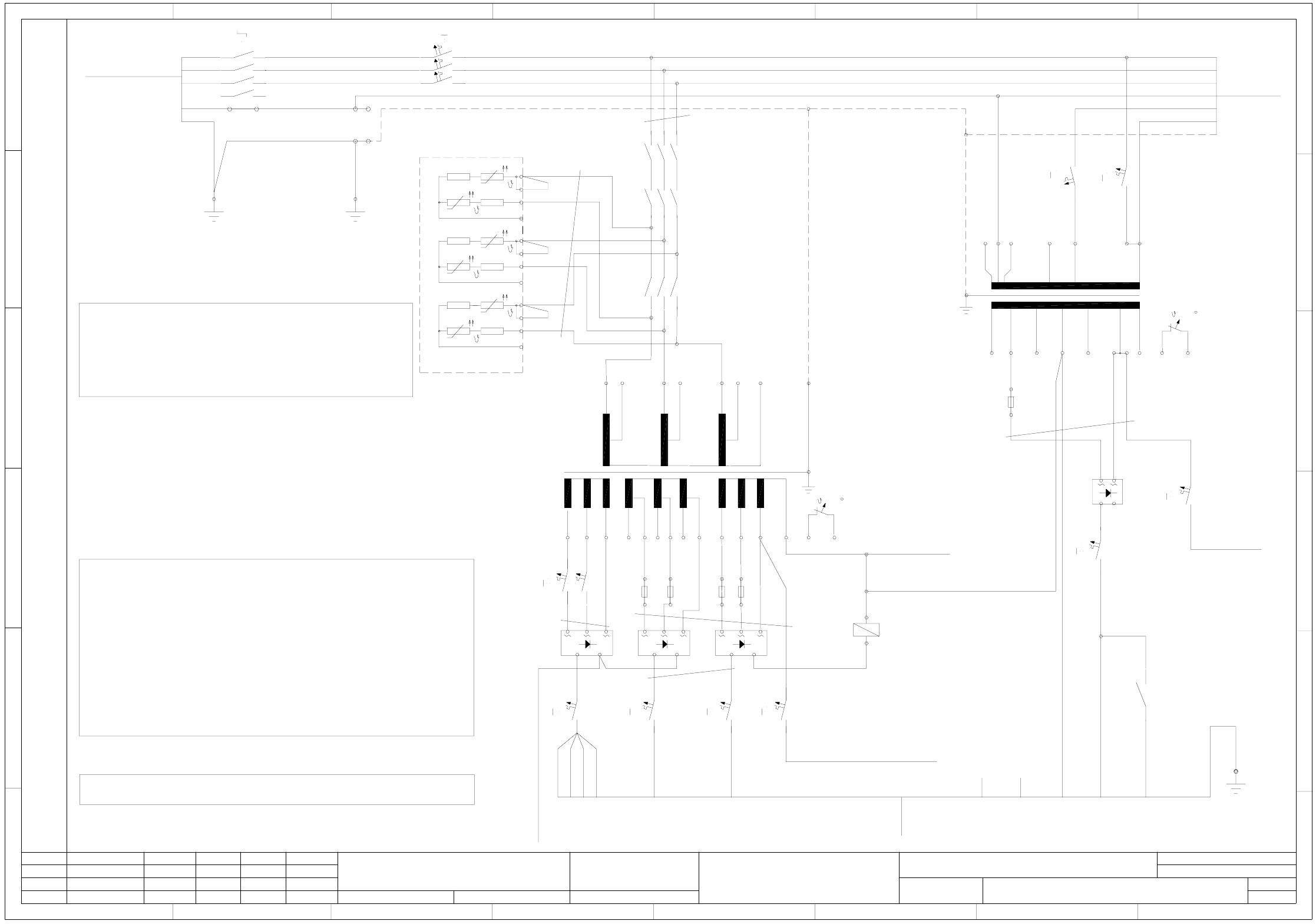
3 - 20
00375503-020101LD3 Power supply unit, circuit diagram
approx. from serial no. 260 (sh. 1 of 2)
78
1234567 8
A
B
C
D
E
F
1
2
K4
3
4
5
6
150VDC
GND
11
12
13
14
21
22
23
24
31
32
33
34
A
B
C
D
E
F
123456
56R 25R
25R 56R
56R 25R
25R 56R
56R 25R
25R 56R
A1(+)
A2(-)
1 1L+ (bk)
2 1L+ (bk)
11 1L+ (bk)
4 1L+ (bk)
3 2L+ (bk)
1U1
1U3
2U1
2V1
2W1
4N
PE
400 204
1V1
1V3
400 204
1W1
1W3
400 204
1N
105 105 105
3V1
3V3
3W1
68 48 68
4U1
4V1
4W1
42 4242 0
6x =130
1
2
0
3W3
48
3U1
3U3
68 48
+-
K4
5 3L+ (bk)
1L- 00324358-xx
70/100VDC 24VDC
10 mm²
Ext. 24VAC emerg.-stop
To sheet 2
Int. 24VAC emerg.-stop
To sheet 2 K1:A1
A
W
G
1
2
b
k
AWG14
AWG12 bk
bk 0.75mm²
AWG14
7
6L+ (bk)
8
2L- (bk)
9
6
10
7L+ (bk)
AWG16 bk
A1
10A
1
2
F9
6A
1
2
F5
6A
1
2
F6
6A
1
2
F7
Power supply base
2
1
3
yegn
Inrush current limitation
1
2
3
4
5
6
7
8
9
AWG16
bk
T2
V1 V2 V3
V5
T1
00356733-xx
To terminal block
To terminal block
If the machine is operated with 208/120V (USA) make sure to:
1.) connect the inrush current limiter A1 in parallel.
(i.e. disconnect wire 3 from 13 and connect to 14, disconnect wire 2 from 12 and connect to 13.
For the other phases, apply this system as appropriate.)
2.) disconnect the infeed for transformer T1 from 230 and connect to 120
disconnect the (1), (2), (3) infeed for transformer T2 from 400 and connect to 208.
X/Y drive Lifting table/star Tape cutter
GND 30/34VDC
DP/Z axes
30/34VDCspare
00356539-xx
To sheet 2 K1:A2
Grounding bolt
X200:PE
AWG14 bk
Front cover
00341193-xx
yegn
X200:PE
T1L1
Q1
T2L2
T3
L3
N´
N
N
N
4
16 A
56
F1
34
12
(2)
(1)
(3)
(6)
Wiring note!
Make sure that the leads to the inrush current limiter A1 are long enough and run them in a way that they can easily be reconnected.
Mark the wires listed below with identification labels:
- To inrush current limiter
- To T1 connectors: 7 and 11
- To T2 connectors: 1U1, 1V1, 1W1 and 3U3, 3V3, 3W3
(1)
(2)
(3)
(1)
(2)
Attention! Note the power supply!
When operating the machine with a modular PCB conveyor (S27HM) reconnect the conductors in this way:
- on transformer T1 - conductors (1) and (2)
Wire (1) from terminal 7 to terminal 13
Wire (2) from terminal 11 to terminal 12
This ensures, that a voltage (6L+) of 34VDC is available at F9.
- on transformer T2 - conductors (4), (5) and (6)
Wire (4) from terminal 3U3 to terminal 3U1
Wire (5) from terminal 3V3 to terminal 3V1
Wire (6) from terminal 3W3 to terminal 3W1
This ensures, that a voltage (2L+) of 100VDC is available at F5.
(4)
(5)
(6)
10A
1
2
F3
6A
2
1
F11
+-
0
10
24
28
10
24
28
230
150
120
0
+5%
-5%
123 4 5 66
7813 9 10
12
11
6x =130
14 15
6A
1
2
F10
(5)
(4)
gnye
bn
bk
wh
bu
rd
gy
(2)
(1)
(3)
(6)
bn
bk
wh
bu
X200:N
Run N wire via main power switch, if required.
(IT network) e.g. France / Italy / USA
Attention! Note the machine type!
00342917-xx (W3)
To line filter
Main power switch
00357898-xx
+-+-
This diagram displays the wiring for the power supply unit when dispatched.
20AT
1
2
F5.1
20AT
1
2
F5.2
1
2
F6.1 20AT
1
2
F6.2 20AT
bk AWG14
20AT
1
2
F9.1
Note on micro-fuses !
Always check the micro-fuses listed below when any of the automatic circuit breakers has tripped:
F5.1, F5.2 or F6.1, F6.2 or F9.1
Please note !
spare
25A-D
1
2
F4.1
3
4
Conveyor, width adjustmt.
1
2
K2
20A
1
2
F4
Shrink the spare wires 6 and 7 individually.
135
246
K11
135
246
K12
besondere für den Fall der Patenterteilung oder GM-Eintragung
pflichten zu Schadenersatz. Alle Rechte vorbehalten, ins
nicht ausdrücklich zugestanden. Zuwiderhandlungen ver-
wertung und Mitteilung ihres Inhalts nicht gestattet, soweit
Weitergabe sowie Vervielfältigung dieser Unterlage,Ver-
Confiado como secrete industrial. Nos reservamos todos los derechos.
Comunicado como segredo empresarial. Reservados todos os direilos.
Confie a titre de secret d´entreprise. Tous droits reserves.
Proprietary data, company confidential. All rights reserved.
L&A EA1 R&D
SIEMENS
Date
Author
Check.
Stand.Status
1 .
1 .
1 .
NameDateModified
Function status
Product status
Document status
20.01.2004
20.01.2004
20.01.2004
Tuth
Tuth
Tuth
Orig.
L&A EA1
20.01.2004
Tuth
Repl. byRepl. f.
00375503-020101LD3
Power supply unit circuit diagram
SIPLACE S-27 HM
2
Sheet
Sh.
1
approx. from serial no. 260