S27HM Circuit Diagrams.pdf - 第111页
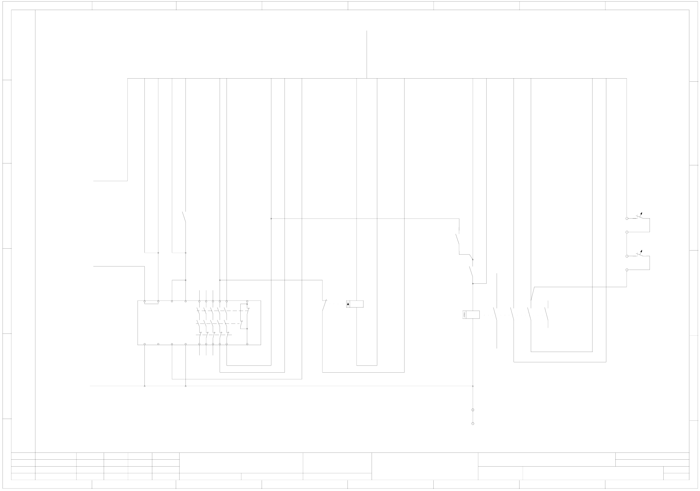
3 - 22 0037553 9-010 101LD3 Power su pply uni t, circu it diagr am, Japan ver sion appr ox. f rom se rial no . 260 (s h. 1 of 2) +- +- +- A1(+) A2(-) K4 5 3L+ ( bk) bk 1L- 00 3243 58-xx 70/100 VDC 24VDC 10 mm² Ext. 24 VA…
3 - 21
00375503-020101LD3 Power supply unit, circuit diagram
approx. from serial no. 260 (sh. 2 of 2)
besondere für den Fall der Patenterteilung oder GM-Eintragung
pflichten zu Schadenersatz. Alle Rechte vorbehalten, ins
nicht ausdrücklich zugestanden. Zuwiderhandlungen ver-
wertung und Mitteilung ihres Inhalts nicht gestattet, soweit
Weitergabe sowie Vervielfältigung dieser Unterlage,Ver-
Confiado como secrete industrial. Nos reservamos todos los derechos.
Comunicado como segredo empresarial. Reservados todos os direilos.
Confie a titre de secret d´entreprise. Tous droits reserves.
Proprietary data, company confidential. All rights reserved.
L&A EA1 R&D
SIEMENS
Date
Author
Check.
Stand.Status
1 .
1 .
1 .
NameDateModified
Function status
Product status
Document status
20.01.2004
20.01.2004
20.01.2004
Tuth
Tuth
Tuth
Orig.
L&A EA1
20.01.2004
Tuth
Repl. byRepl. f.
00375503-020101LD3
Power supply unit circuit diagram
SIPLACE S-27 HM
2
Sheet
Sh.
2
approx. from serial no. 260
78
1234567 8
A
B
C
D
E
F
13 23 33
14 24 34
51
52
A1 Y34Y33Y11
Y21 Y43 Y44
41
42
Y10 Y12
Y22 PEA2
A1(+)
A2(-)
21
22
K3
gy
wh
bn
gn
bu
wh&gn
bk
A
B
C
D
E
F
123456
vi
bn&gn
ye
wh&gy
gy&bn
pk&bn
00321113-xx
To ext. emerg.-stop circuit
24V~
24V~
To On button
From emerg.-stop circuit
24V-
From emerg.-stop circuit
To key-operated switch
To signaling circuit Control On K1
From On button
To signaling circuit Software release
Software release
Software release
To sheet 1
GND
To sheet 1
F7:2 24V~
AWG 16bk
Sheet 1 5/B
MP1 M
43
44
K3
gy&pk
rd&bu
ye&bn
rd
pk
50VDC release
50VDC release
Sheet 1 8/D
13
14
K2
On button
To signaling circuit Control On K2
On button
A1
A2
K11
13521
24622
K11
A1
A2
K12
13521
24622
K12
Sheet 1 5/B
3RT1015
3RT1015
3RT1015
K2
A1
A2
13513
24614
Sheet 2 6/C
3TK2825
K1
Power
Channel 1
Channel 2
14
13
F10:2 24V~
AWG 16bk
K3
To sheet 1
Connecting terminals
wh&ye
+24V-
14
15
T1
1
2
T2
wh&pk
bk 0.75
Temperature monitoring T1 and T2
Temperature switch
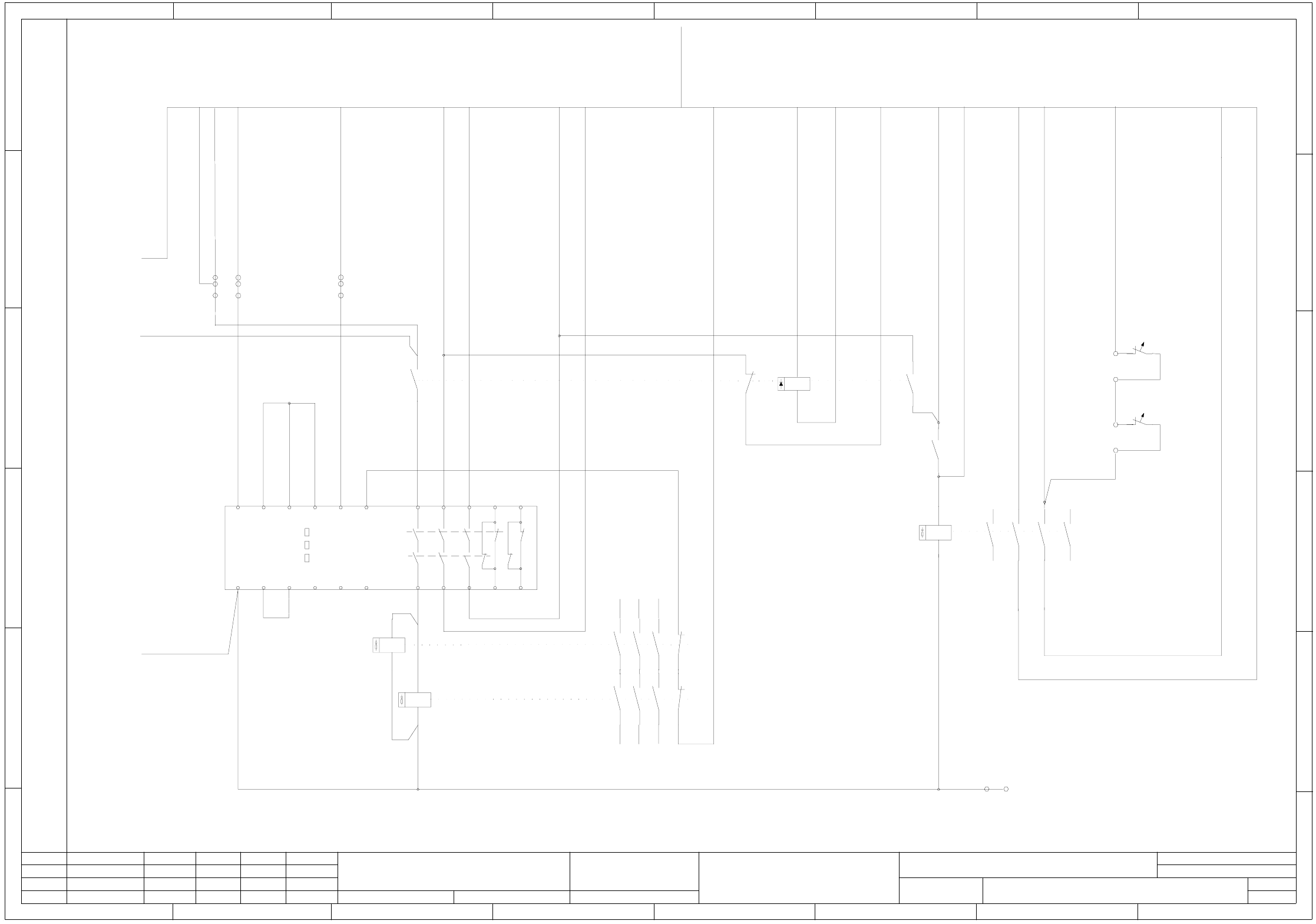
3 - 22
00375539-010101LD3 Power supply unit, circuit diagram, Japan version
approx. from serial no. 260 (sh. 1 of 2)
+-+-+-
A1(+)
A2(-)
K4
5 3L+ (bk)
bk
1L- 00324358-xx
70/100VDC 24VDC
10 mm²
Ext. 24VAC emerg.-stop
To sheet 2
Int. 24VAC emerg.-stop
To sheet 2
bk
bk
AWG12
AWG14
AWG12
bk
bk
bk 0.75mm²
AWG14
9
6L+ (bk)
8
2L- (bk)
10
7L+ (bk)
AWG16 bk
A1
6A
1
2
F11
3
4
6A
1
2
F12
3
4
6A
1
2
F13
3
4
10A
1
2
F3
3
4
5
6
16A
1
2
F2
3
4
5
6
10A
1
2
F9
6A
1
2
F10
6A
1
2
F5
6A
1
2
F6
6A
1
2
F7
20A
1
2
F4
Power supply base
2
1
3
yegn
Inrush current limitation
1
2
3
4
5
6
7
8
9
AWG16
bk
1
2
3
4
5
6
7
8
9
AWG16
bk
T2
V1 V2 V3
V4
T1
A2
Inrush current limitation
00356733-xx
To terminal block
00356540-xx
To terminal block
Attention !
If the machine is operated with 208/120V (USA) or 200/115V (Japan) make sure to:
1.) connect the inrush current limiters A1 and A2 in parallel.
(i.e. disconnect wire 3 from 13 and connect to 14, disconnect wire 2 from 12 and connect to 13.
For the other phases, apply this system as appropriate.)
2.) disconnect the infeed for transformers T1 and T2 from the 400V terminals and connect to the 204V terminals.
Connectors ( 1 ), ( 2 ), ( 3 )
Power circuit Lifting table/star Tape cutter
GND 30/34VDC
DP/Z axes
30/34VDC
Width adjustmt.
Power pack
Control unit
Station computer
(500VA)
CO tables
(1200VA)
WPC
00356539-xx
AWG14 bk
1
yegn
2
3
4
5
6
7
8
9
To sheet 2 K2:A2
Grounding bolt
X200:PE
10
AWG14 bk
Front cover
00359822-xx
X200:PE
X200:PE
yegn
X200:PE
T1L1
Q1
T2L2
T3
L3
N´
N
N
N
4
16 A
56
F1
34
12
12
11
13
14
11
12
13
14
(1)
(2)
(3)
CO tables
WPC
(1)
(2)
(3)
(4)
(5)
(6)
(4)
(5)
(6)
1
2
F5.1
20AT
AWG14
bk
25A-D
1
2
F4.1
3
4
1
2
F9.1 20AT
7
6
(bk)
sparespare
(bk)
Shrink individually
1
2
F5.2
20AT
1
2
F6.1
20AT
1
2
F6.2
20AT
1
2
F9.2 20AT
This diagram displays the wiring for the power supply unit when dispatched.
besondere für den Fall der Patenterteilung oder GM-Eintragung
pflichten zu Schadenersatz. Alle Rechte vorbehalten, ins
nicht ausdrücklich zugestanden. Zuwiderhandlungen ver-
wertung und Mitteilung ihres Inhalts nicht gestattet, soweit
Weitergabe sowie Vervielfältigung dieser Unterlage,Ver-
Confiado como secrete industrial. Nos reservamos todos los derechos.
Comunicado como segredo empresarial. Reservados todos os direilos.
Confie a titre de secret d´entreprise. Tous droits reserves.
Proprietary data, company confidential. All rights reserved.
L&A EA1 R&D
SIEMENS
Date
Author
Check.
Stand.Status
1 .
1 .
1 .
NameDateModified
Function status
Product status
Document status
26.01.2004
26.01.2004
26.01.2004
Tuth
Tuth
Tuth
Orig.
L&A EA1 R&D
26.01.2004
Tuth
Repl. byRepl. f.
00375539-010101LD3
Power supply unit circuit diagram
SIPLACE S-27 HM
2
Sheet
Sh.
1
Japan version
When operating the machine with a modular PCB conveyor reconnect the conductors in this way:
Wire (6) from terminal 2W3 to terminal 2W1
This ensures, that a voltage (2L+) of 100VDC is available at F5.
Wire (6) from terminal 3W3 to terminal 3W1
Wire (5) from terminal 3V3 to terminal 3V1
Wire (4) from terminal 3U3 to terminal 3U1
This ensures, that a voltage (6L+) of 34VDC is available at F9.
- on transformer T2 - conductors (4), (5) and (6)
Wire (5) from terminal 2V3 to terminal 2V1
Wire (4) from terminal 2U3 to terminal 2U1
- on transformer T1 - conductors (4), (5) and (6)
Attention !
- To T1 connectors: 1U1, 1V1, 1W1, 2U3, 2V3, 2W3
- To T2 connectors: 1U1, 1V1, 1W1, 3U3, 3V3, 3W3
Mark the wires listed below with identification labels:
Make sure that the leads to the inrush current limiters A1 and A2 are long enough and run them in a way that they can easily be reconnected.
- To inrush current limiter
Wiring note!
approx. from serial no. 260
(800VA)
(500VA)
+-
A1(+)
A2(-)
K5
1 1L+ (bk)
2 1L+ (bk)
11 1L+ (bk)
4 1L+ (bk)
3 2L+ (bk)
400
1U1
1U5
1U6
2N
1U4
1U3
1V1
1V4
1V5
1V4
1V3
1W1
1W5
1W6
1W4
1W3
1N
X200:PE
230 204 150 400 230 204 400 230 204 150
0
0
2W1
2W4
1542
3x =130°
1
2
48
2W3
2V1
2V4
1542
48
2V3
2U3
2U4
15
42
48
2U3
2U1
1U1
1U3
2U1
2V1
2W1
4N
X200:PE
400 204
1V1
1V3
400 204
1W1
1W3
400 204
1N
105 105 105
3V1
3V3
3W1
68 48 68
4U1
4V1
4W1
42 42 42 0
6x =130°
1
2
0
3W3
48
3U1
3U3
68 48
8
1234567 8
A
B
C
D
E
F
1
2
K4
3
4
5
6
150VDC
GND
13 23 33
14 24 34
K1
11
12
13
14
21
22
23
24
31
32
33
34
1
2
K2
A
B
C
D
E
F
1234567
56R 25R
25R 56R
56R 25R
25R 56R
56R 25R
25R 56R
1
2
K5
3
4
5
6
11
12
13
14
21
22
23
24
31
32
33
34
56R 25R
25R 56R
56R 25R
25R 56R
56R 25R
25R 56R
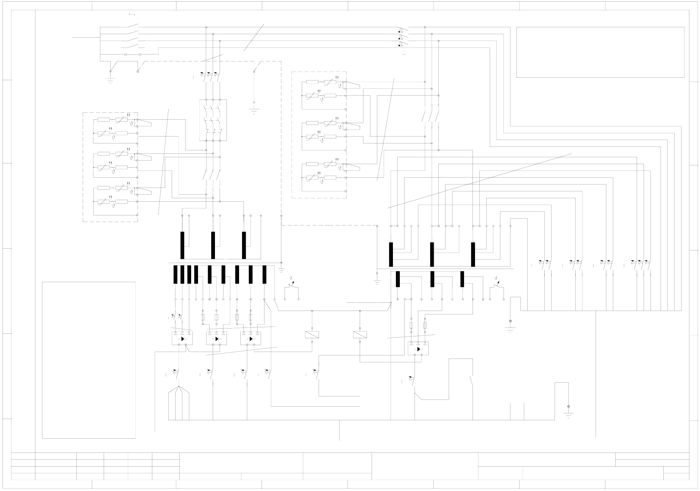
3 - 23
00375539-010101LD3 Power supply unit, circuit diagram, Japan version
approx. from serial no. 260 (sh. 2 of 2)
8
1234567 8
A
B
C
D
E
F
13 23 33 43 53
14 24 34 44 54
65
66
L1 X1 X3 X5
L2 X2 X4 X6
3TK2805
A1(+)
A2(-)
21
22
K3
A
B
C
D
E
F
1234567
13
14
K3
43
44
K3
gy
wh
bn
gn
bu
wh&gn
bk
vi
bn&gn
ye
wh&gy
gy&bn
pk&bn
gy&pk
rd&bu
wh&ye
ye&bn
Sheet 1 7/E
rd
pk
00321113-xx
To ext. emerg.-stop circuit
24V~
24V~
To On button
From emerg.-stop circuit
24V-
From emerg.-stop circuit
To key-operated switch
To signaling circuit Control On K1
From On buttonFrom On button
To signaling circuit Software release
Software release
Software release
50VDC release
+24V-
50VDC release
To sheet 1
F10:2 24V~
To sheet 1
GND
To sheet 1
F7:2 24V~
AWG 16bk
AWG 16bk
K1
K2
14
15
T1
1
2
T2
wh&pk
bk 0.75
Temperature monitoring T1 and T2
Temperature switch
Sheet 1 5/B
A1
A2
13513
24614
MP1
M
Sheet 1 7/E
13
14
K2
Sheet 2 6/D
3RT1015
On button
To signaling circuit Control On K2
On button
besondere für den Fall der Patenterteilung oder GM-Eintragung
pflichten zu Schadenersatz. Alle Rechte vorbehalten, ins
nicht ausdrücklich zugestanden. Zuwiderhandlungen ver-
wertung und Mitteilung ihres Inhalts nicht gestattet, soweit
Weitergabe sowie Vervielfältigung dieser Unterlage,Ver-
Confiado como secrete industrial. Nos reservamos todos los derechos.
Comunicado como segredo empresarial. Reservados todos os direilos.
Confie a titre de secret d´entreprise. Tous droits reserves.
Proprietary data, company confidential. All rights reserved.
L&A EA1 R&D
SIEMENS
Date
Author
Check.
Stand.Status
1 .
1 .
1 .
NameDateModified
Function status
Product status
Document status
26.01.2004
26.01.2004
26.01.2004
Tuth
Tuth
Tuth
Orig.
L&A EA1 R&D
26.01.2004
Tuth
Repl. byRepl. f.
00375539-010101LD3
Power supply unit circuit diagram
SIPLACE S-27 HM
2
Sheet
Sh.
2
Japan version
Sheet 1 5/B
approx. from serial no. 260