S27HM Circuit Diagrams.pdf - 第127页
4 - 13 0035639 5-040 201 TD3 Powe r supply , elect rical d esign, O ption fo r Japan, appr ox. up to ser ial no . 259 ( sh. 2 of 2) 1. 4. 21.08.2001 26.06.2001 Tut h Tut h 26.06.2001 Tut h Siplace S-27 H M Placement Sy s…
4 - 12
00356395-040201TD3 Power supply, electrical design, Option for Japan,
approx. up to serial no. 259 (sh. 1 of 2)
1.
4.
21.08.2001
26.06.2001
Tuth
Tuth 26.06.2001
Tuth
Siplace S-27 HM Placement System
Power supply, electrical design,
Option for Japan
approx. up to serial no. 259
00356395-040201TD3
08.02.2001 Tuth
2.
SIEMENS
L&A EA
Status Modified Date Name Standard Orig. Repl.f. Repl. by
Document status
Product status
Function status Date
Author
Check.
Sheet
Sh.
W
e
i
t
e
r
g
a
b
e
s
o
w
i
e
V
e
r
v
i
e
l
f
ä
l
t
i
g
u
n
g
d
i
e
s
e
r
U
n
t
e
r
l
a
g
e
,
V
e
r
-
w
e
r
t
u
n
g
u
n
d
M
i
t
t
e
i
l
u
n
g
i
h
r
e
s
I
n
h
a
l
t
s
n
i
c
h
t
g
e
s
t
a
t
t
e
t
,
s
o
w
e
i
t
n
i
c
h
t
a
u
s
d
r
ü
c
k
l
i
c
h
z
u
g
e
s
t
a
n
d
e
n
.
Z
u
w
i
d
e
r
h
a
n
d
l
u
n
g
e
n
v
e
r
-
p
f
l
i
c
h
t
e
n
z
u
S
c
h
a
d
e
n
e
r
s
a
t
z
.
A
l
l
e
R
e
c
h
t
e
v
o
r
b
e
h
a
l
t
e
n
,
i
n
s
b
e
s
o
n
d
e
r
e
f
ü
r
d
e
n
F
a
l
l
d
e
r
P
a
t
e
n
t
e
r
t
e
i
l
u
n
g
o
d
e
r
G
M
-
E
i
n
t
r
a
g
u
n
g
P
r
o
p
r
i
e
t
a
r
y
d
a
t
e
,
c
o
m
p
a
n
y
c
o
n
f
i
d
e
n
t
i
a
l
.
A
l
l
r
i
g
h
t
s
r
e
s
e
r
v
d
.
C
o
n
f
i
e
a
t
i
t
r
e
d
e
s
e
c
r
e
t
d
´
e
n
t
r
e
p
r
i
s
e
.
T
o
u
s
d
r
o
i
t
s
r
e
s
e
r
v
e
s
.
C
o
m
u
n
i
c
a
d
o
c
o
m
o
s
e
g
r
e
d
o
e
m
p
r
e
s
a
r
i
a
l
.
R
e
s
e
r
v
a
d
o
s
t
o
d
o
s
o
s
d
i
r
e
i
l
o
s
.
C
o
n
f
i
a
d
o
c
o
m
o
s
e
c
r
e
t
e
i
n
d
u
s
t
r
i
a
l
.
N
o
s
r
e
s
e
r
v
a
m
o
s
t
o
d
o
s
l
o
s
d
e
r
e
c
h
o
s
.
A
B
C
D
E
F
1 2 3 4 5 6 7 8
1
2 3 4 5 6 7 8
A
B
C
D
E
F
1
2
L1 X1 X3 X5 13 23 33 43 57 65
L2 X2 X4 X6 14 24 34 44 58 66
K2
Ein
On
Frei
Ready
L1 X1 X3 X5 13 23 33 43 53 65
L2 X2 X4 X6 14 24 34 44 54 66
K1
Netz
Power
Kanal 1
Channel 1
Kanal 2
Channel 2
1
2
4
3
6
51
2
4
3
6
51
2
4
3
6
5
1
2
4
3
1
2
4
3
1
2
1
2
4
31
2
1
2
1
2
1
2
1
2
F10
F7
F11
F1 F2 F3
F4 F5
F6 F8
F9 F12 F13
85mm
6
5
m
m
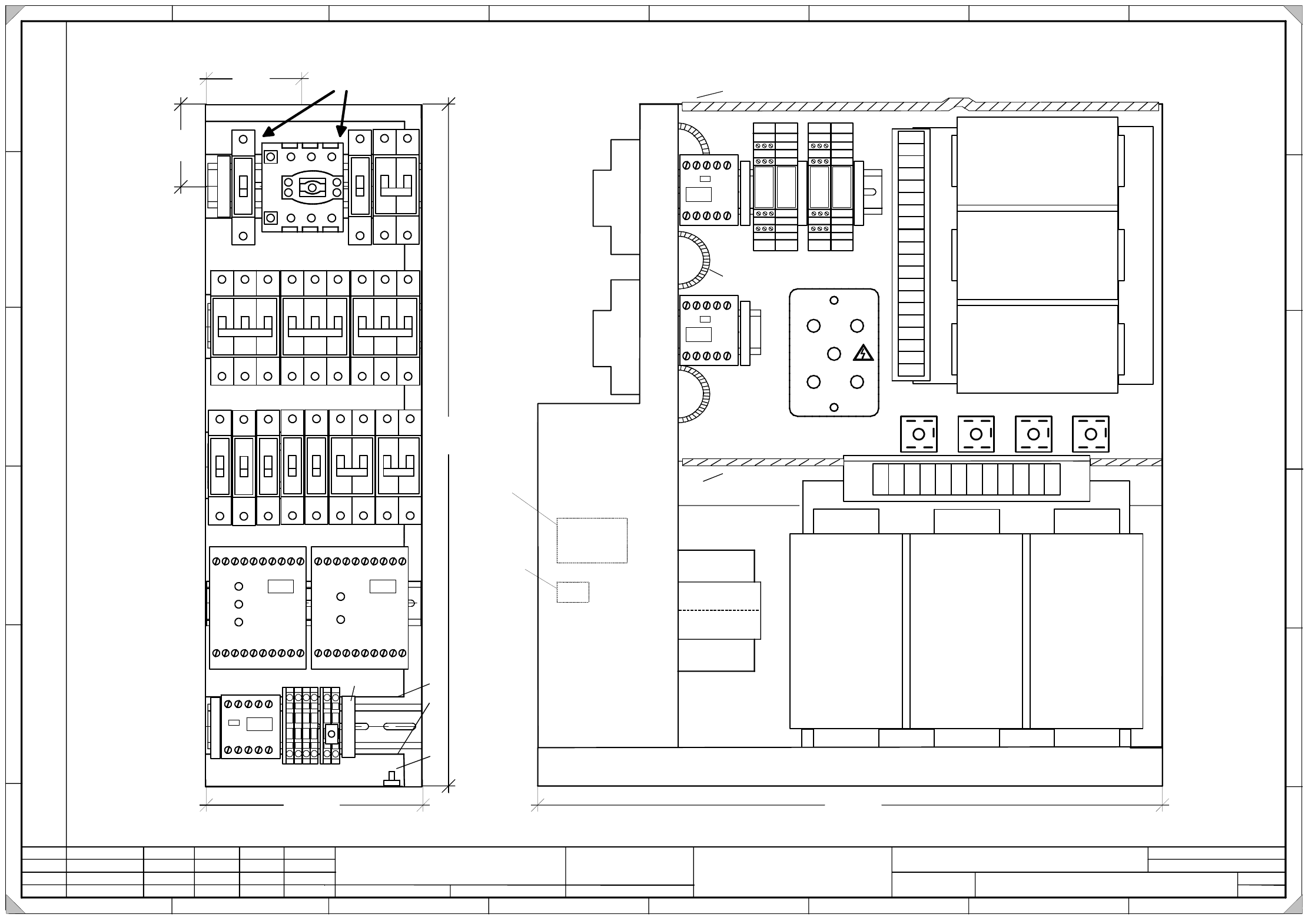
On the top hat rail, the main switch
must have a play of max. 2mm on each side!
5
3
5
m
m
170mm
G
r
o
u
n
d
b
o
l
t
Cables must not protrude from the upper edge of the frame !
K4
490mm
Edge protection
14 24 34
12 22 32
13 23 33
11 21 31
14 24 34
12 22 32
13 23 33
11 21 31
1
2
V3
V1
V2 V4 V5
A1 A2
Edge protection
E
H
6
-
1
0
m
m
E
d
g
e
p
r
o
t
e
c
t
i
o
n
E
H
1
0
m
m
E
H
6
-
1
0
m
m
E
H
6
-
1
0
m
m
Edge protection
K5
E
H
6
m
m
K3
P
E
P
E
P
E
P
E
M
M
X
2
0
0
EH10mm
246
135
N
N
E
H
6
-
1
0
m
m
6A
6A 6A
10A
16A 16A
20A
6A
6A
6A 10A
6A
6A
A
B
A
.
I
d
e
n
t
i
f
i
c
a
t
i
o
n
l
a
b
e
l
B
.
I
n
s
p
e
c
t
i
o
n
l
a
b
e
l
4 - 13
00356395-040201TD3 Power supply, electrical design, Option for Japan,
approx. up to serial no. 259 (sh. 2 of 2)
1.
4.
21.08.2001
26.06.2001
Tuth
Tuth 26.06.2001
Tuth
Siplace S-27 HM Placement System
Power supply, electrical design,
Option for Japan
approx. up to serial no. 259
00356395-040201TD3
08.02.2001 Tuth
2.
SIEMENS
L&A EA
Status Modified Date Name Standard Orig. Repl.f. Repl. by
Document status
Product status
Function status Date
Author
Check.
Sheet
Sh.
W
e
i
t
e
r
g
a
b
e
s
o
w
i
e
V
e
r
v
i
e
l
f
ä
l
t
i
g
u
n
g
d
i
e
s
e
r
U
n
t
e
r
l
a
g
e
,
V
e
r
-
w
e
r
t
u
n
g
u
n
d
M
i
t
t
e
i
l
u
n
g
i
h
r
e
s
I
n
h
a
l
t
s
n
i
c
h
t
g
e
s
t
a
t
t
e
t
,
s
o
w
e
i
t
n
i
c
h
t
a
u
s
d
r
ü
c
k
l
i
c
h
z
u
g
e
s
t
a
n
d
e
n
.
Z
u
w
i
d
e
r
h
a
n
d
l
u
n
g
e
n
v
e
r
-
p
f
l
i
c
h
t
e
n
z
u
S
c
h
a
d
e
n
e
r
s
a
t
z
.
A
l
l
e
R
e
c
h
t
e
v
o
r
b
e
h
a
l
t
e
n
,
i
n
s
b
e
s
o
n
d
e
r
e
f
ü
r
d
e
n
F
a
l
l
d
e
r
P
a
t
e
n
t
e
r
t
e
i
l
u
n
g
o
d
e
r
G
M
-
E
i
n
t
r
a
g
u
n
g
P
r
o
p
r
i
e
t
a
r
y
d
a
t
e
,
c
o
m
p
a
n
y
c
o
n
f
i
d
e
n
t
i
a
l
.
A
l
l
r
i
g
h
t
s
r
e
s
e
r
v
d
.
C
o
n
f
i
e
a
t
i
t
r
e
d
e
s
e
c
r
e
t
d
´
e
n
t
r
e
p
r
i
s
e
.
T
o
u
s
d
r
o
i
t
s
r
e
s
e
r
v
e
s
.
C
o
m
u
n
i
c
a
d
o
c
o
m
o
s
e
g
r
e
d
o
e
m
p
r
e
s
a
r
i
a
l
.
R
e
s
e
r
v
a
d
o
s
t
o
d
o
s
o
s
d
i
r
e
i
l
o
s
.
C
o
n
f
i
a
d
o
c
o
m
o
s
e
c
r
e
t
e
i
n
d
u
s
t
r
i
a
l
.
N
o
s
r
e
s
e
r
v
a
m
o
s
t
o
d
o
s
l
o
s
d
e
r
e
c
h
o
s
.
A
B
C
D
E
F
1 2 3 4 5 6 7 8
1
2 3 4 5 6 7 8
A
B
C
D
E
F
00356540-xx
00356539-xx
00356733-xx
00321113-xx
00324358-xx
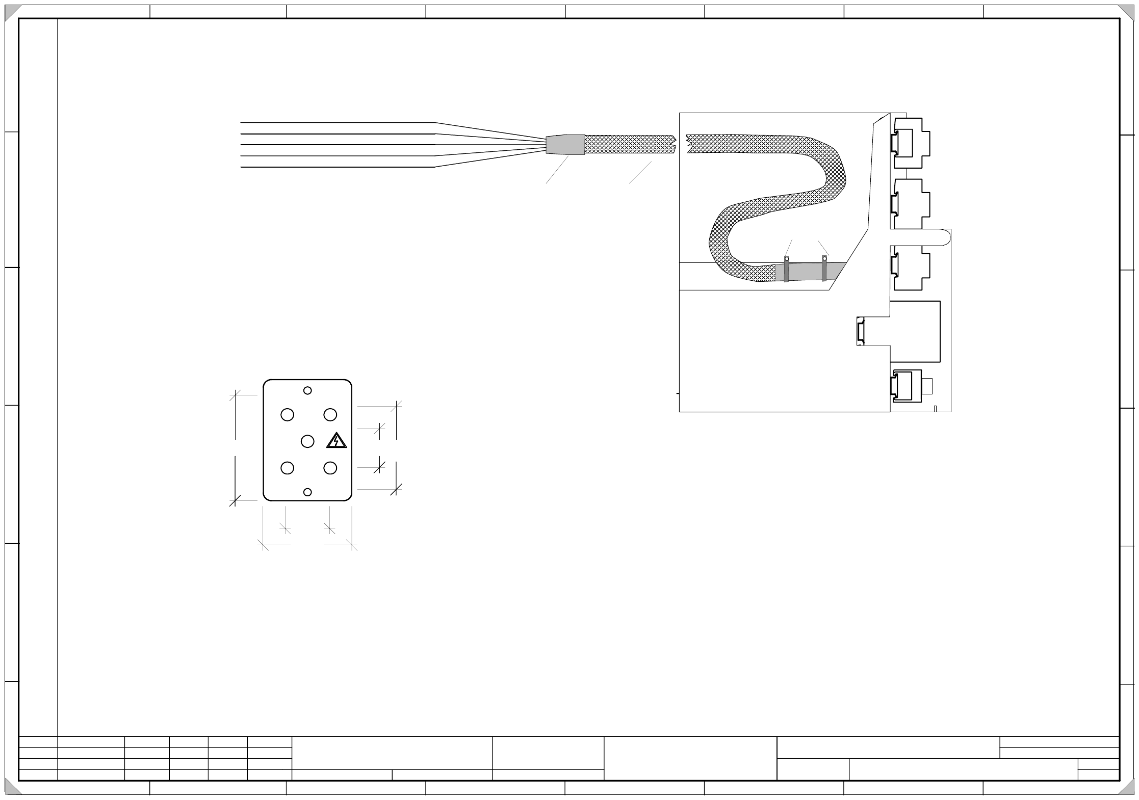
10cm heat shrinkable tubing
1.10 m prot. hose
28mm
70mm
1
0
0
m
m
8
5
m
m
4
0
m
m
Cover for bridge rectifier
Material : Makrolon transparent 1.5mm
Holes : symmetrical 2x dia.= 4.5 mm
4x dia.= 6 mm
Break and chamfer edges
Fit the cover for the bridge rectifier V1 using
M4 distance bolts with a length of 50 mm.
2
2
Fit 2 cable clamps
20cm heat shrinkable tubing
Please note !
Mold-in bolts, fastening elements and screws may not protrude
from the rear panel of the base.
Make sure that there is enough space for the cable harness to
form a loop in the respective area.
4 - 14
00356643-010301TD3 Design terminal block, voltages, approx. up to serial no. 224
1.
1.
17.10.2001 Tuth
17.10.2001
Tuth
00356643-010301TD3
25.11.2000 Tuth
3.
1
Siplace S-27HM SMD Placement System
Terminal panel design, voltages
approx. up to serial no. 224
Status Modified Date Name Standard
Document status
Product status
Function status Date
Author
Check.
SIEMENS
L&A EA
Orig. Repl. f. Repl. by
Sheet
Sh.
W
e
i
t
e
r
g
a
b
e
s
o
w
i
e
V
e
r
v
i
e
l
f
ä
l
t
i
g
u
n
g
d
i
e
s
e
r
U
n
t
e
r
l
a
g
e
,
V
e
r
-
w
e
r
t
u
n
g
u
n
d
M
i
t
t
e
i
l
u
n
g
i
h
r
e
s
I
n
h
a
l
t
s
n
i
c
h
t
g
e
s
t
a
t
t
e
t
,
s
o
w
e
i
t
n
i
c
h
t
a
u
s
d
r
ü
c
k
l
i
c
h
z
u
g
e
s
t
a
n
d
e
n
.
Z
u
w
i
d
e
r
h
a
n
d
l
u
n
g
e
n
v
e
r
-
p
f
l
i
c
h
t
e
n
z
u
S
c
h
a
d
e
n
e
r
s
a
t
z
.
A
l
l
e
R
e
c
h
t
e
v
o
r
b
e
h
a
l
t
e
n
,
i
n
s
b
e
s
o
n
d
e
r
e
f
ü
r
d
e
n
F
a
l
l
d
e
r
P
a
t
e
n
t
e
r
t
e
i
l
u
n
g
o
d
e
r
G
M
-
E
i
n
t
r
a
g
u
n
g
P
r
o
p
r
i
e
t
a
r
y
d
a
t
e
,
c
o
m
p
a
n
y
c
o
n
f
i
d
e
n
t
i
a
l
.
A
l
l
r
i
g
h
t
s
r
e
s
e
r
v
d
.
C
o
n
f
i
e
a
t
i
t
r
e
d
e
s
e
c
r
e
t
d
´
e
n
t
r
e
p
r
i
s
e
.
T
o
u
s
d
r
o
i
t
s
r
e
s
e
r
v
e
s
.
C
o
m
u
n
i
c
a
d
o
c
o
m
o
s
e
g
r
e
d
o
e
m
p
r
e
s
a
r
i
a
l
.
R
e
s
e
r
v
a
d
o
s
t
o
d
o
s
o
s
d
i
r
e
i
l
o
s
.
C
o
n
f
i
a
d
o
c
o
m
o
s
e
c
r
e
t
e
i
n
d
u
s
t
r
i
a
l
.
N
o
s
r
e
s
e
r
v
a
m
o
s
t
o
d
o
s
l
o
s
d
e
r
e
c
h
o
s
.
A
B
C
D
E
F
1 2 3 4 5 6 7 8
1
2 3 4 5 6 7 8
A
B
C
D
E
F
X2
X1
X4
X3
X6
X5
4321
123456
X7
1234567
89
12345
6
K1 K2 K3
X2
X1
1234567
891011
1234567
89
12345
6
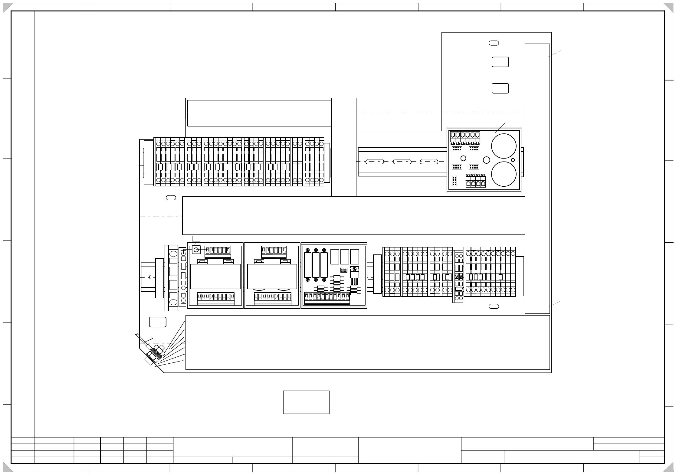
Cable duct 65x 30 l= 175mm
x
x
x
C
a
b
l
e
d
u
c
t
6
5
X
3
0
l
=
1
1
5
m
m
C
Cable duct 65 x 66 l= 460mm
XXXX
x
Cable duct 65 x46 l= 425mm
xx
X
X
X
X
C
a
b
l
e
d
u
c
t
6
5
X
3
0
l
=
3
3
5
m
m
X
X
X
X
X
X
X
X
X
A
B
00341194-xx
A
2
1
11 1 1 1
55 5 8 95
22 33
6 7 8
X
2
0
7
M
10
A3
A4
A5
A1
1
L2L1 L2L1 L3 L3 N NN 21 21 3 3 4 4 65 65 97 87 10 11
PE PE PE PE
X
2
0
6
7
44
Option
PEPE
R1
PE
Fit the following labels:
A: Identification label
B: Inspection label Identification: testing engineer, month, year
C: Ground label
D: Space for voltage label from NAFTA-label set (applies to USA only)
SIEMENS PLEA 1
00356643-xx
AA-BBBB-CCCC
Assembly inscription according to guideline VA-F-510-001
Font size 2.5mm; material Scotchcal 3698-E (color A1 RAL 9006)
Label size LxW 40x20mm
AA Manufacturer / location acc. to SN 37040
BBBB Date (year / month / day) acc. to SN 01007
CCCC Series number
Ground connection
acc. to construction specs 00343603-xx
Length of cable ducts: +/- 5mm
X means to break off one rib
from the cable duct
Leave 4 ribs on top
Leave 2 ribs on bottom
DIN 7980 split washer
DIN 439 nut
DIN 125 washer
Annular cable lug
SN 70093 contact washer
DIN 439 nut
Screw