S27HM Circuit Diagrams.pdf - 第155页
5 - 19 00335522-020101ND3 Machine controller M54, KSP-M54/COM292 (sh. 2 of 2) SIEMENS AG 1. 1. 2. F 1 Doc. s tatus Product status Function status Tek Tek Tek 13.11.98 13.11.98 13.11.98 E D 23 02.07.1998 Seer L&A EA1 …
5 - 18
00335522-020101ND3 Machine controller M54, KSP-M54/COM292 (sh. 1 of 2)
SIEMENS AG
1.
1.
2.
F
1
Doc. status
Product status
Function status
Tek
Tek
Tek
13.11.98
13.11.98
13.11.98
E
D
23
02.07.1998
Seer
L&A EA1
4
C
B
A
1234
SMD Placement System SIPLACE HS60
00335522-020101ND3
5
Machine controller, M54
KSP-M54/COM292
678
2
+
=
Sheet
Sh.
1
F
E
D
567
C
B
8
A
Stand.Status Modified NameDate Orig. Replacement for Replaced by
Check.
Author
Date
5 - 19
00335522-020101ND3 Machine controller M54, KSP-M54/COM292 (sh. 2 of 2)
SIEMENS AG
1.
1.
2.
F
1
Doc. status
Product status
Function status
Tek
Tek
Tek
13.11.98
13.11.98
13.11.98
E
D
23
02.07.1998
Seer
L&A EA1
4
C
B
A
1234
SMD Placement System SIPLACE HS60
00335522-020101ND3
5
Machine controller M54
678
2
+
=
Sheet
Sh.
2
F
E
D
567
C
B
8
A
KSP-M54/COM292
Stand.Status Modified NameDate Orig. Replacement for Replaced by
Check.
Author
Date
5 - 20
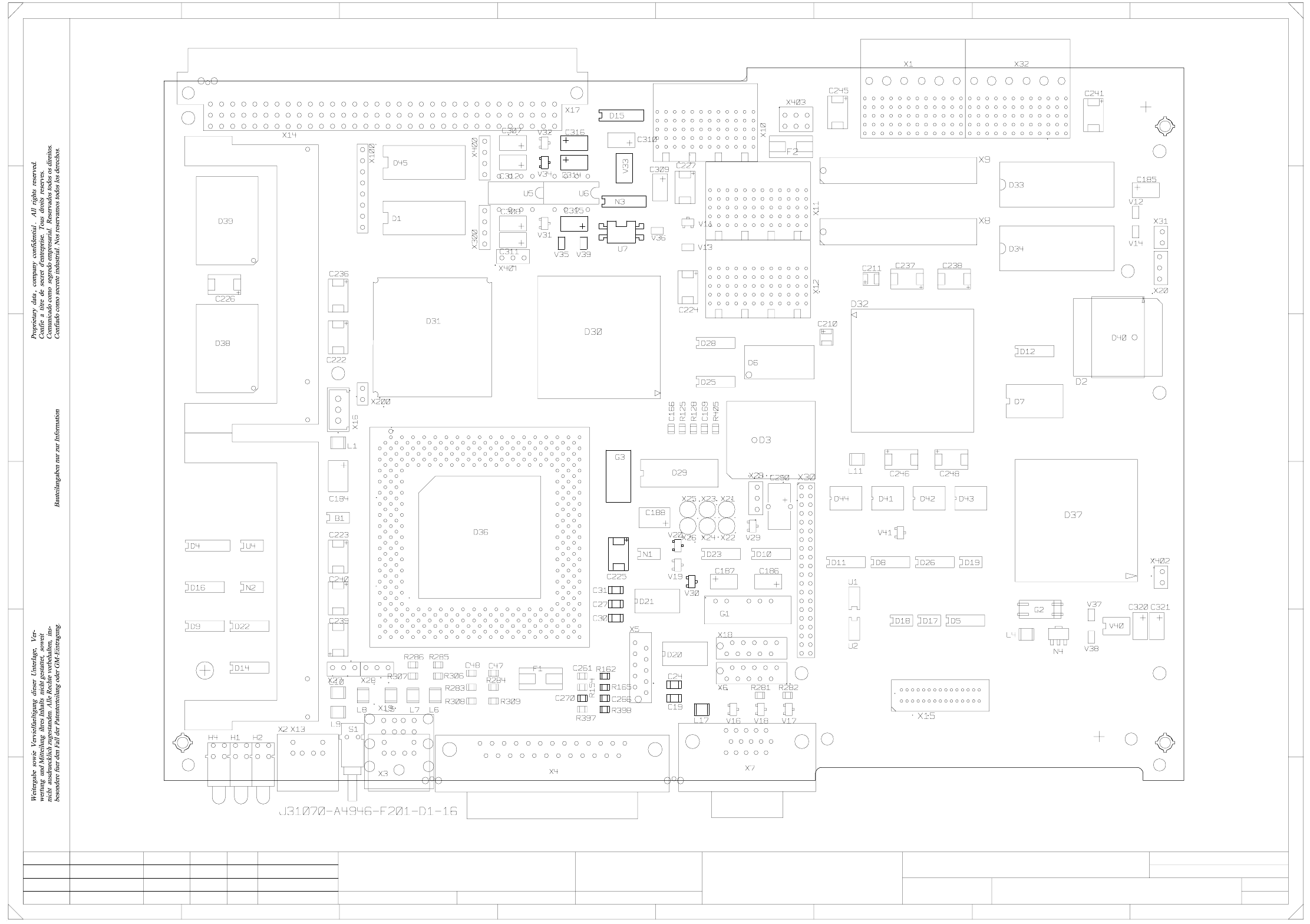
00344485-080101ND4 Printed circuit board 877, processor board 80C515C (sh. 1 of 2)
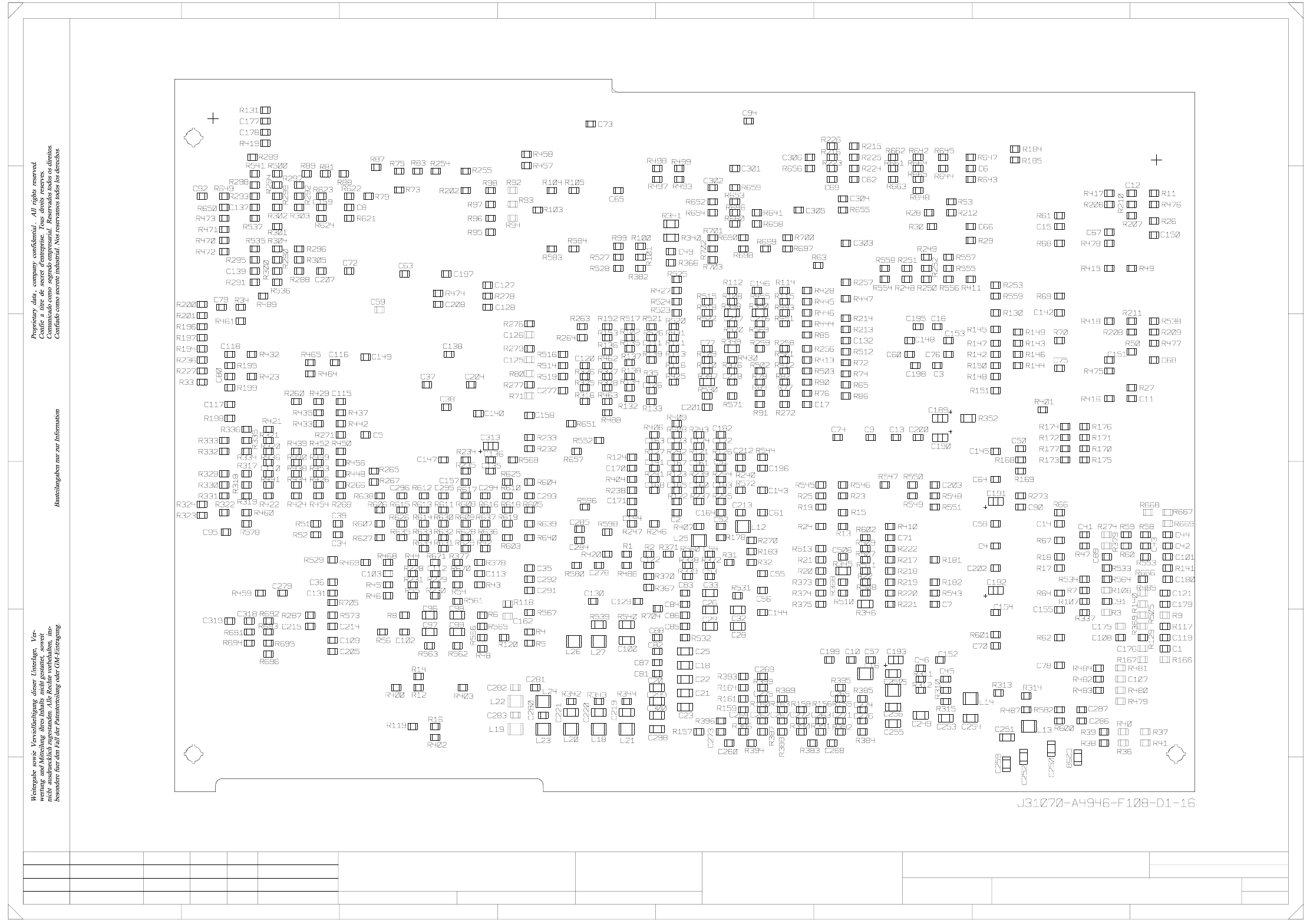
00344485-080101ND4 Printed circuit board 877, processor board 80C515C (sh. 2 of 2)
KL06.07.00--------03
--------04 27.11.02 KL
KL14.02.03
08.09.03 KL--------
--------05
06 07.12.98
Klose
SIEMENS
SEDM D&D MCH
S-27 HM
G32918-K0113-U081-*-0017
00344485-080101ND4
1 +
Ω
WP_EEPROM
120
VISION ID
CAN_ID0
CAN_ID1
VISION ID
OFF
OFF
OFF
OFF
ON
OFF
OFF
ON
OFF
OFF
OFF
OFF
OFF
ON
ON
ON
8
7
6
5
4
3
2
1
S1
CAN message can
not be sent
Overflow in receive
Processor board received message,
rather than command
Power failure
Firmware error
buffer of CAN bus
Transmission
Transmission
Hardware error
on processor board
2
3
4
F
5
6
1
Any
0
error
error
Status
OK
Check gantry address jumpers
Check power failure wiring
or COM module of control unit
Goes out automatically if transmission
at processor board
Check RESET signal,
otherwise processor error
-
at processor board
Hardware reset
Hardware reset
Fault in CAN bus wiring
is repeated successfully
Remedy
-
When initializing: transition fromA
BIOS to application module
When booting: head processorb
remains in BIOS mode
7-segment display
-
-
pflichten zu Schadenersatz. Alle Rechte vorbehalten, ins
besondere für den Fall der Patenterteilung oder GM-Eintragung
wertung und Mitteilung ihres Inhalts nicht gestattet, soweit
Weitergabe sowie Vervielfältigung dieser Unterlage,Ver-
nicht ausdrücklich zugestanden. Zuwiderhandlungen ver-
Proprietary date, company confidential. All rights reserved.
Confie a titre de secret d'entreprise. Tous droits reserves.
Confiado como secrete industrial. Nos reservamos todos los derechos.
Comunicado como segredo empresarial. Reservados todos os direitos.
LED
15V
5V (analog)
V1 (green)
V2 (green)
V3 (red) Red (RESET µC)
Off: normal operation
C = ESD label
B = Inspection label
A = Identification label
terminator
TEST MODE
TEST MODE
Gantry 1 Gantry 2
Sheet
8-layer printed circuit board
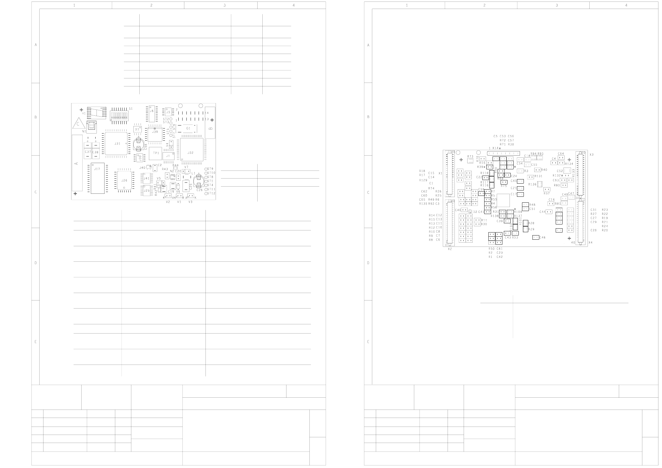
Component mounting diagram, component side
Printed circuit board 877
Processor board 80C515C
Stat. Modified Date Name
Date
Name
Scale 1:1
06
03
04
05
--------
--------
--------
--------
08.09.03
06.07.00
27.11.02
14.02.03
KL
KL
KL
KL
SEDM D&D MCH
SIEMENS
07.12.98
Klose
00344485-080101ND4
G32918-K0113-U081-*-0017
S-27 HM
2 -
X4
X3
X1
X2
pflichten zu Schadenersatz. Alle Rechte vorbehalten, ins
besondere für den Fall der Patenterteilung oder GM-Eintragung
wertung und Mitteilung ihres Inhalts nicht gestattet, soweit
Weitergabe sowie Vervielfältigung dieser Unterlage,Ver-
nicht ausdrücklich zugestanden. Zuwiderhandlungen ver-
Proprietary date, company confidential. All rights reserved.
Confie a titre de secret d'entreprise. Tous droits reserves.
Confiado como secrete industrial. Nos reservamos todos los derechos.
Comunicado como segredo empresarial. Reservados todos os direitos.
* Do not fit components
Connector Assembly
Stat. Modified Date
Date
8-layer printed circuit board
Component mounting diagram, solder side
Printed circuit board 877
Processor board 80C515C
Sheet
M 1:1
Name
Name
X26 Gantry - head distributor, 00354430-xx
X25 Gantry - head distributor, 00354430-xx
X24 Gantry - head distributor, 00354430-xx
X23 Gantry - head distributor, 00354430-xx