S27HM Circuit Diagrams.pdf - 第181页
6 - ii SIPLACE S -27 HM Detail ed Circuit Diagrams Folder 05/2005 US Editi on
SIPLACE S-27 HM Detailed Circuit Diagrams Folder
05/2005 US Edition
6 - i
6 Pneumatic diagrams
00363749-010401XD1 Pneumatic diagram S-27 HM 6 - 1
00328647-010201XD3 Tape cutter, pneumatically operated 6 - 2
00358663-020401XD4 Cylinder - valve combination, lifting table 6 - 3
00353744-030101XD3 Pneumatic diagram, nozzle changer CP12, S27 6 - 4
00329906-010101EX3 Pneumatic symbols 6 - 5
6 - ii
SIPLACE S-27 HM Detailed Circuit Diagrams Folder
05/2005 US Edition
6 - 1
6 Pneumatic diagrams
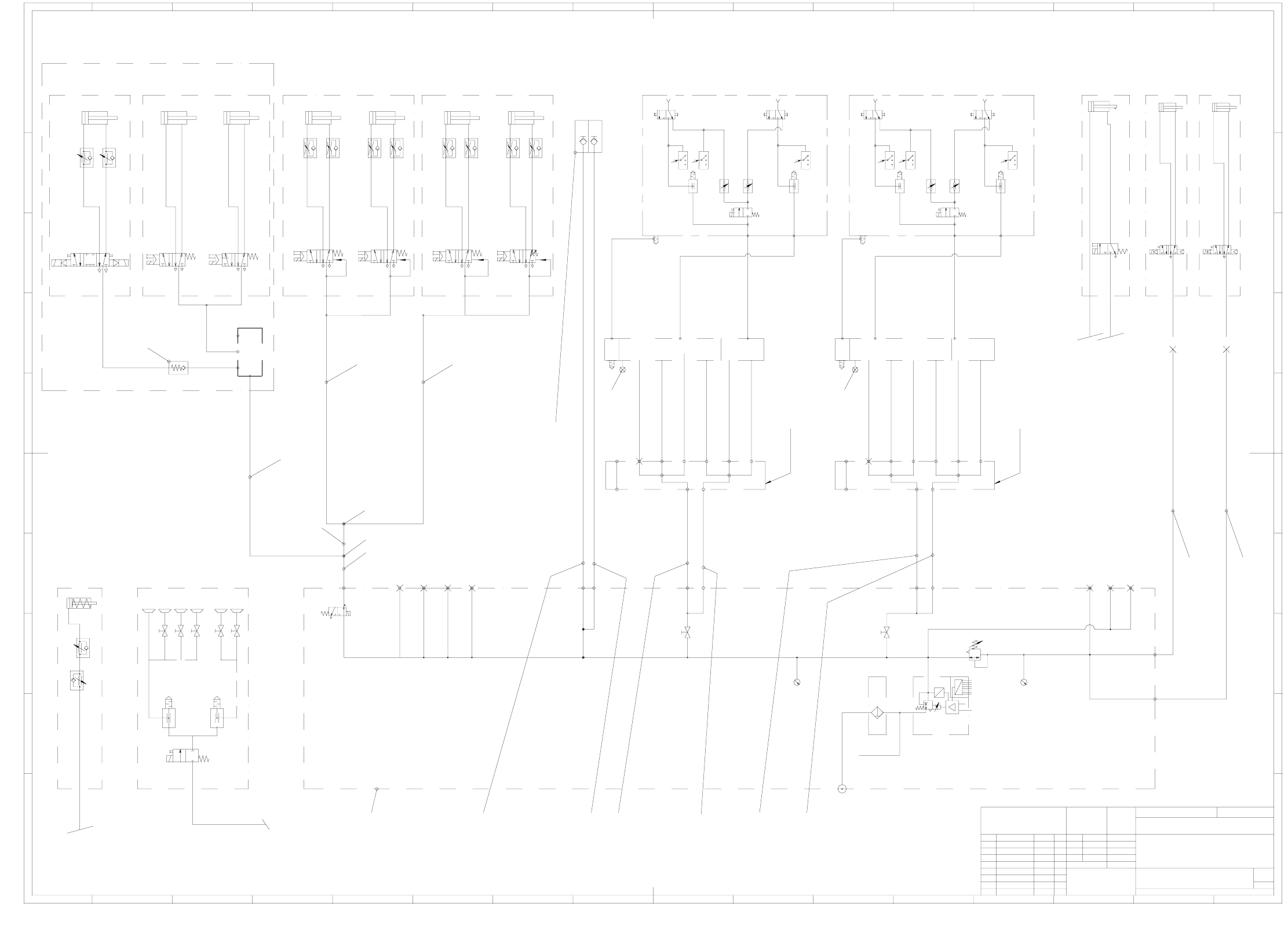
00363749-010401XD1 Pneumatic diagram S-27 HM
X
5
1
4
3
2
Ab
5
1
4
3
2
Ab
Cyl.2Cyl.1Cyl.2Cyl.1
A
PR
b
5
1
4
3
2
Ab
5
1
4
3
2
Ab
5
1
4
3
2
Ab
5
1
4
3
2
Ab
K
I
H
G
F
E
D
C
B
A
K
I
H
G
F
E
D
C
B
A
151413121110987654321
16151413121110987654321
16
EZH-2,5/9-10
A
D
P
V
X
a patent or the registration of a utility model or design.
damages. All rights are reserved in the event of the grant of
out express authority. Offenders are liable to the payment of
or communication of the contents thereof, are forbidden with-
Copying of this document, and giving it to others and the use
Schadenersatz. Alle Rechte für den Fall der Patenterteilung
ausdrücklich zugestanden. Zuwiderhandlungen verpflichten zu
tung und Mitteilung ihres Inhalts nicht gestattet, soweit nicht
Weitergabe sowie Vervielfältigung dieser Unterlage, Verwer-
oder GM-Eintragung vorbehalten.
00363749-010401XD1
Pneumatic diagram S27 HM
SIPLACE S-27 HM
---------
acc. to ISO 2768 mH
Degree of accuracy
Dimens. variations:
Author
Check.
Stand.
medium
S27 HM new
CHN 11796
CHN 12269
400723,12621,12212
ModifiedStatus
FS 01
PS 02
PS 03
PS 04 27.10.03 Fu.
10.02.03 Fu.
21.05.02 Fu.
05.04.01 Fu.
Date Name
SIEMENS
AUT 5
28.05.01
Date Name
Futterer
(Drawing number)
Main no.
(Model or swage no.)
(Material, semi-fin. products)
Scale
(Unmachined part no.)
---
F
A1
PSFS SDTDS
Format
1
Sh.
Sheet
1
(Option)
Substrate centering
(Option)
Vacuum tooling
PU4/1500
PCB conveyor
Lifting table Width adjustment
PUN6
(H-QS-6)
PUN2
Distributor
right
Pneumatic tape cutterPneumatic tape cutter
left
Valve 1 Valve 2 Valve 1 Valve 2
Ø 40 ; stroke 30Ø 40 ; stroke 30Ø 40 ; stroke 30Ø 40 ; stroke 30
23
24
PUN6/1500
PUN6/2600
33
37
PUN8/1300
31 (QSY-8)
38
32 (QSY-8-6)
B16
right
Table
left
Table
Bulk case feeder connection
(Option)
19
PUN6/1900B15
171820 12
11
6 . 5
DLM2 12-6 DLM2 12-6
Placement circuit
Vacuum
Nozzle Ø 1mm
Forced air Placement circuit
Forced air Reject circuit
Holding circuit
Vacuum
Nozzle Ø 1.5mm
Placement circuit
Vacuum
Nozzle Ø 1mm
Forced air Placement circuit
Forced air Reject circuit
Vacuum
Holding circuit
Nozzle Ø 1.5mm
03006332-0X
Filter block
Air distributor /
03006332-0X
Filter block
Air distributor /
Gantry 1 distributor
Cable and hose carrier
7x hose
Gantry 2 distributor
QSC-4H
7x hose
Cable and hose carrier
QSC-4H
PUN6/2800
B14
E3
E2
PUN8/1200
E1
PUN8/1200
B12
B13
PUN8/2400
B11
B10
PUN8/2400
E1
E2
E3
A7
A6
A3
A5
A4
A2
A1
A7
A6
A3
A5
A4
A2
A1
Gantry 2
B9
B6
B5
B4
Gantry 1
p = 5.2 bar
p max. = 10 bar
p min. = 6 bar
NOM value
8 bit
external
internal
digital
p = 2.5 ± 0.2 bar
B8
B7
B3
B2
B1
PCB stopper
(Option)
Nozzle changer
(right)
Nozzle changer
(left)
5.1 bar
5.1 bar
PUN4/1500
PUN4/2800
B1
401
3635