S27HM Circuit Diagrams.pdf - 第39页
1 - 26 0035447 5-010 101LD3 Servo unit, S-27 HM, overview (sh. 1 of 2) 1. 1. 25.05.2000 25.05.2000 Tut h Tut h 04.05.2001 Tut h Siplace S27 HM SMD Placem ent Sy stem Ser vo un it , over vie w 00354475 -01010 1LD3 25.05.2…
1 - 25
00328647-010101LD3 Tape cutter, max. tape height 15 mm
=
Sheet
SIEMENS
Sh.
+
SIPLACE S-27 HM
00313400
00322071 / 00322072
Tek
Tek
01.
01.
01.
10.07.97
10.07.97
25.11.97
10.07.1997
Eschenweck
#
00328647-010101LD3
L&A EA
Tek
1
1
Product status
Doc. status
Function status
To interface
Tape cutter
Max. tape height: 15 mm
Cable: power supply unit - tape cutter
Cable: interface (left / right) - tape cutter
component supply
00322064-xx
right
To
terminal panel, voltages
00375221-xx
(2x24VAC / 0V)
(dq)
00329699
Control board, tape cutter
Cable: control board tape cutter - valve
00332901
00332900
Proximity switch with cable for tape cutter II
Proximity switch with cable for tape cutter II
00332900
Cable: control board tape cutter - valve
00332901
Proximity switch with cable for tape cutter I
00332899
00332899
Proximity switch with cable for tape cutter I
Left
valve
cylinder
Left
Front
proximity switch
Rear
proximity switch
Front
proximity switch
proximity switch
Rear
Right
cylinder
valve
Right
Stand.Status DateModified Name
Orig. Replaced byRepl. f.
Author
Date
Check.
To interface
left
00322063-xx
component supply
(2x24VAC / 0V)
00356643-xx
terminal panel, voltages
To
See page 5-12
See page 3-16 See page 3-18
See page 2-37 See page 2-36
1 - 26
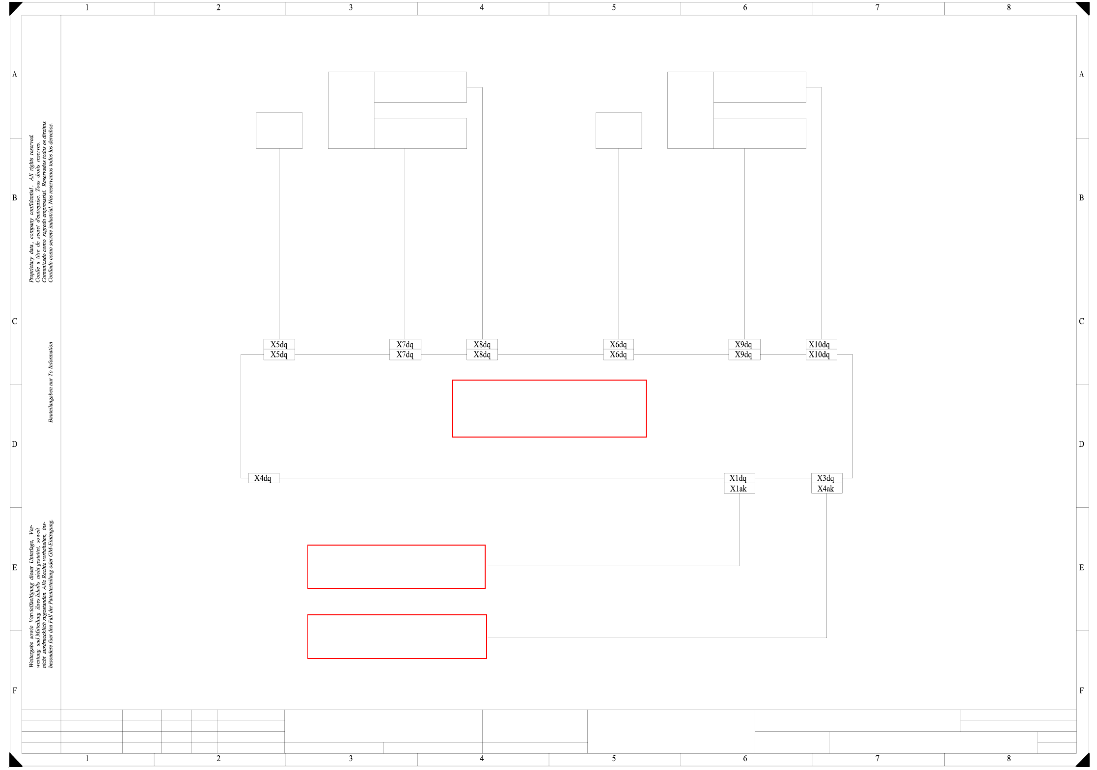
00354475-010101LD3 Servo unit, S-27 HM, overview (sh. 1 of 2)
1.
1.
25.05.2000
25.05.2000
Tuth
Tuth 04.05.2001
Tuth
Siplace S27 HM SMD Placement System
Servo unit, overview
00354475-010101LD3
25.05.2000 Tuth
1.
SIEMENS AG
L&A EA
Status Modified Date Name Standard Orig. Repl.f. Repl. by
Document status
Product status
Function status Date
Author
Check.
Sheet
Sh.
W
e
i
t
e
r
g
a
b
e
s
o
w
i
e
V
e
r
v
i
e
l
f
ä
l
t
i
g
u
n
g
d
i
e
s
e
r
U
n
t
e
r
l
a
g
e
,
V
e
r
-
w
e
r
t
u
n
g
u
n
d
M
i
t
t
e
i
l
u
n
g
i
h
r
e
s
I
n
h
a
l
t
s
n
i
c
h
t
g
e
s
t
a
t
t
e
t
,
s
o
w
e
i
t
n
i
c
h
t
a
u
s
d
r
ü
c
k
l
i
c
h
z
u
g
e
s
t
a
n
d
e
n
.
Z
u
w
i
d
e
r
h
a
n
d
l
u
n
g
e
n
v
e
r
-
p
f
l
i
c
h
t
e
n
z
u
S
c
h
a
d
e
n
e
r
s
a
t
z
.
A
l
l
e
R
e
c
h
t
e
v
o
r
b
e
h
a
l
t
e
n
,
i
n
s
b
e
s
o
n
d
e
r
e
f
ü
r
d
e
n
F
a
l
l
d
e
r
P
a
t
e
n
t
e
r
t
e
i
l
u
n
g
o
d
e
r
G
M
-
E
i
n
t
r
a
g
u
n
g
P
r
o
p
r
i
e
t
a
r
y
d
a
t
e
,
c
o
m
p
a
n
y
c
o
n
f
i
d
e
n
t
i
a
l
.
A
l
l
r
i
g
h
t
s
r
e
s
e
r
v
d
.
C
o
n
f
i
e
a
t
i
t
r
e
d
e
s
e
c
r
e
t
d
´
e
n
t
r
e
p
r
i
s
e
.
T
o
u
s
d
r
o
i
t
s
r
e
s
e
r
v
e
s
.
C
o
m
u
n
i
c
a
d
o
c
o
m
o
s
e
g
r
e
d
o
e
m
p
r
e
s
a
r
i
a
l
.
R
e
s
e
r
v
a
d
o
s
t
o
d
o
s
o
s
d
i
r
e
i
l
o
s
.
C
o
n
f
i
a
d
o
c
o
m
o
s
e
c
r
e
t
e
i
n
d
u
s
t
r
i
a
l
.
N
o
s
r
e
s
e
r
v
a
m
o
s
t
o
d
o
s
l
o
s
d
e
r
e
c
h
o
s
.
A
B
C
D
E
F
1 2 3 4 5 6 7 8
1
2 3 4 5 6 7 8
A
B
C
D
E
F
0
0
3
2
1
5
3
9
-
x
x
0
0
3
2
1
5
4
1
-
x
x
(
W
1
)
0
0
3
2
1
5
4
4
-
x
x
(
W
1
)
0
0
3
2
1
5
4
1
-
x
x
(
W
2
)
0
0
3
2
1
5
4
4
-
x
x
(
W
2
)
X30aaX29aaX28aa
0
0
3
2
1
5
6
5
-
x
x
0
0
3
2
1
5
6
7
-
x
x
(
W
1
)
0
0
3
2
1
5
6
9
-
x
x
(
W
1
)
0
0
3
2
1
5
6
7
-
x
x
(
W
2
)
0
0
3
2
1
5
6
9
-
x
x
(
W
2
)
X30baX29baX28ba
X34aa X34ba
0
0
3
2
1
5
7
1
-
x
x
0
0
3
2
1
5
4
7
-
x
x
X2 X3 X4
0
0
3
0
0
1
6
3
-
x
x
0
0
3
0
0
1
6
4
-
x
x
0
0
3
0
0
1
8
2
-
x
x
B
a
l
l
a
s
t
c
i
r
c
u
i
t
X13
A16
a2
a4
a6
a8
Star point 007 1L-
c2
c4
c6
c8
Star point 009 1L+
S
e
r
v
o
c
o
n
t
r
o
l
l
e
r
d
p
1
-
a
x
i
s
(
G
a
n
t
r
y
1
)
B
a
c
k
p
l
a
n
e
d
p
1
-
a
x
i
s
(
G
a
n
t
r
y
1
)
X
1
X
1
v
f
SP head
A3 A20
X
4
v
f
X
3
v
f
X
2
v
f
(vf)
S
e
r
v
o
c
o
n
t
r
o
l
l
e
r
z
-
a
x
i
s
(
G
a
n
t
r
y
1
)
B
a
c
k
p
l
a
n
e
z
-
a
x
i
s
(
G
a
n
t
r
y
1
)
X
1
X
1
v
d
SP head
A4 A21
X
4
v
d
X
3
v
d
X
2
v
d
(vd)
S
e
r
v
o
c
o
n
t
r
o
l
l
e
r
S
t
a
r
-
a
x
i
s
(
G
a
n
t
r
y
1
)
B
a
c
k
p
l
a
n
e
S
t
a
r
a
x
i
s
(
G
a
n
t
r
y
1
)
X
1
X
1
v
c
SP head
A5 A22
X
4
v
c
X
3
v
c
X
2
v
c
(vc)
S
e
r
v
o
c
o
n
t
r
o
l
l
e
r
d
p
1
-
a
x
i
s
(
G
a
n
t
r
y
2
)
B
a
c
k
p
l
a
n
e
d
p
1
-
a
x
i
s
(
G
a
n
t
r
y
2
)
X
1
X
1
v
r
SP head
A8 A25
X
4
v
r
X
3
v
r
X
2
v
r
(vr)
S
e
r
v
o
c
o
n
t
r
o
l
l
e
r
z
-
a
x
i
s
(
G
a
n
t
r
y
2
)
B
a
c
k
p
l
a
n
e
z
-
a
x
i
s
(
G
a
n
t
r
y
2
)
X
1
X
1
v
p
SP head
A9 A26
X
4
v
p
X
3
v
p
X
2
v
p
(vp)
S
e
r
v
o
c
o
n
t
r
o
l
l
e
r
S
t
a
r
a
x
i
s
(
G
a
n
t
r
y
2
)
B
a
c
k
p
l
a
n
e
S
t
a
r
a
x
i
s
(
G
a
n
t
r
y
2
)
X
1
X
1
v
o
SP head
A10 A27
X
4
v
o
X
3
v
o
X
2
v
o
(vo)
1
2
C
r
a
s
h
b
o
a
r
d
X
1
A15
X
1
1
X
1
1
b
X
1
1
a
X
1
1
c
X
1
1
d
X
1
1
e
X
1
1
f
X
1
1
g
P
o
w
e
r
s
u
p
p
l
y
u
n
i
t
+
/
-
1
5
V
A17
1L-
4
6
8
10
12
14
16
18
20
22
24
26
28
30
32
6L+
-15V
-15V
-15V
-15V
-15V
-15V
1L-
+15V
+15V
+15V
+15V
+15V
+15V
Input
Output
X12
Output
Input
0
0
3
2
4
3
5
9
-
x
x
To terminal panels
S
t
a
r
p
o
i
n
t
0
0
7
1
L
-
G
r
o
u
n
d
0
0
3
2
1
5
8
2
-
x
x
G
r
o
u
n
d
b
o
l
t
R
i
g
h
t
s
i
d
e
p
a
n
e
l
1 - 27
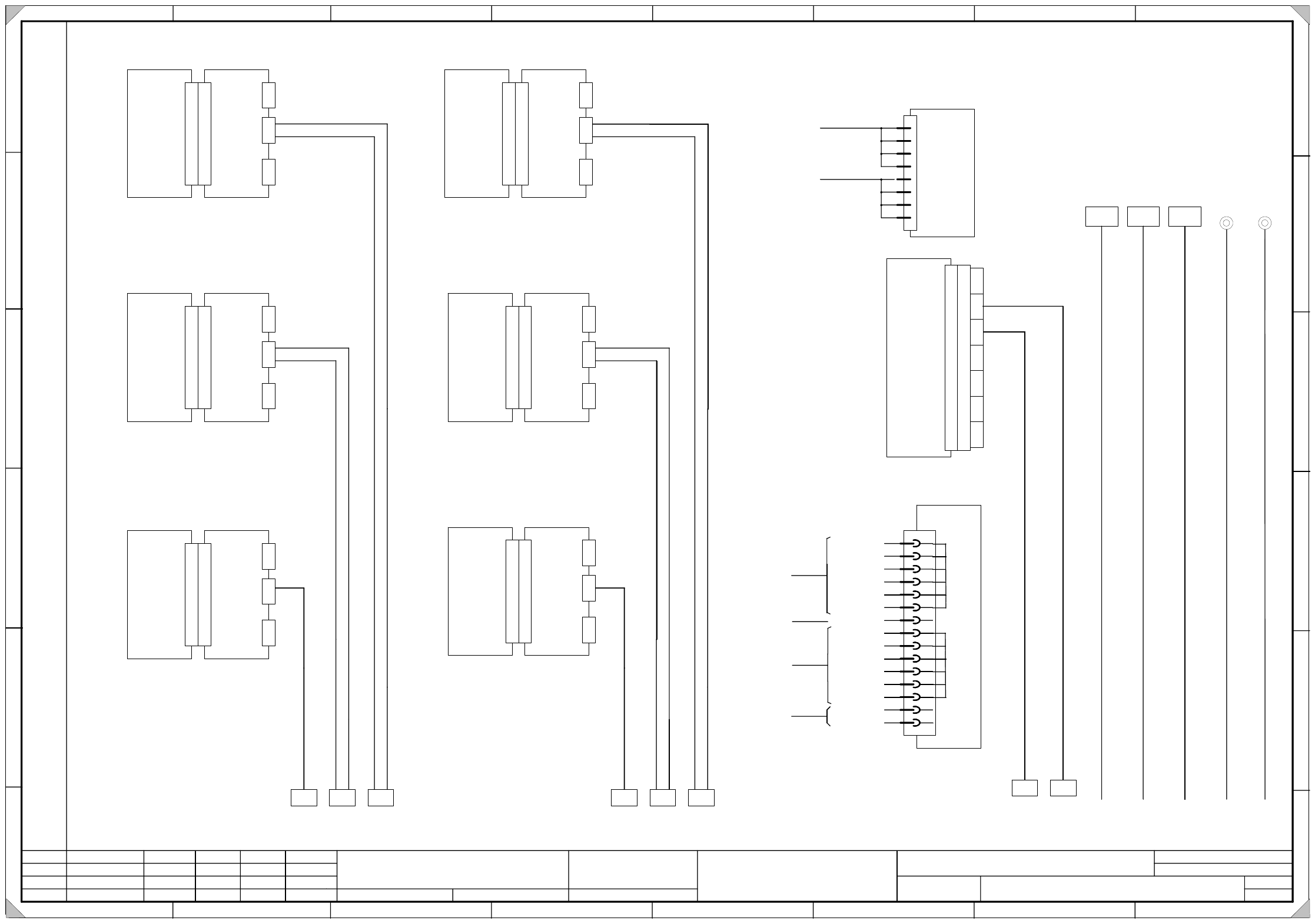
00354475-010101LD3 Servo unit, S-27 HM, overview (sh. 2 of 2)
1.
1.
25.05.2000
25.05.2000
Tuth
Tuth 04.05.2001
Tuth
Siplace S27 HM SMD Placement System
Servo unit, overview
00354475-010101LD3
25.05.2000 Tuth
1.
SIEMENS AG
L&A EA
Status Modified Date Name Standard Orig. Repl.f. Repl. by
Document status
Product status
Function status Date
Author
Check.
Sheet
Sh.
W
e
i
t
e
r
g
a
b
e
s
o
w
i
e
V
e
r
v
i
e
l
f
ä
l
t
i
g
u
n
g
d
i
e
s
e
r
U
n
t
e
r
l
a
g
e
,
V
e
r
-
w
e
r
t
u
n
g
u
n
d
M
i
t
t
e
i
l
u
n
g
i
h
r
e
s
I
n
h
a
l
t
s
n
i
c
h
t
g
e
s
t
a
t
t
e
t
,
s
o
w
e
i
t
n
i
c
h
t
a
u
s
d
r
ü
c
k
l
i
c
h
z
u
g
e
s
t
a
n
d
e
n
.
Z
u
w
i
d
e
r
h
a
n
d
l
u
n
g
e
n
v
e
r
-
p
f
l
i
c
h
t
e
n
z
u
S
c
h
a
d
e
n
e
r
s
a
t
z
.
A
l
l
e
R
e
c
h
t
e
v
o
r
b
e
h
a
l
t
e
n
,
i
n
s
b
e
s
o
n
d
e
r
e
f
ü
r
d
e
n
F
a
l
l
d
e
r
P
a
t
e
n
t
e
r
t
e
i
l
u
n
g
o
d
e
r
G
M
-
E
i
n
t
r
a
g
u
n
g
P
r
o
p
r
i
e
t
a
r
y
d
a
t
e
,
c
o
m
p
a
n
y
c
o
n
f
i
d
e
n
t
i
a
l
.
A
l
l
r
i
g
h
t
s
r
e
s
e
r
v
d
.
C
o
n
f
i
e
a
t
i
t
r
e
d
e
s
e
c
r
e
t
d
´
e
n
t
r
e
p
r
i
s
e
.
T
o
u
s
d
r
o
i
t
s
r
e
s
e
r
v
e
s
.
C
o
m
u
n
i
c
a
d
o
c
o
m
o
s
e
g
r
e
d
o
e
m
p
r
e
s
a
r
i
a
l
.
R
e
s
e
r
v
a
d
o
s
t
o
d
o
s
o
s
d
i
r
e
i
l
o
s
.
C
o
n
f
i
a
d
o
c
o
m
o
s
e
c
r
e
t
e
i
n
d
u
s
t
r
i
a
l
.
N
o
s
r
e
s
e
r
v
a
m
o
s
t
o
d
o
s
l
o
s
d
e
r
e
c
h
o
s
.
A
B
C
D
E
F
1 2 3 4 5 6 7 8
1
2 3 4 5 6 7 8
A
B
C
D
E
F
D
y
n
.
b
r
a
k
e
X
-
a
x
i
s
(
G
a
n
t
r
y
1
)
B
a
c
k
p
l
a
n
e
X
-
a
x
i
s
(
G
a
n
t
r
y
1
)
X
2
v
a
SP head
A11 A18
X
5
v
a
X
4
v
a
X
3
v
a
1L+ / GND
S
e
r
v
o
c
o
n
t
r
o
l
l
e
r
X
-
a
x
i
s
(
G
a
n
t
r
y
1
)
X
1
v
a
SP head
A1
X
1
v
a
X
2
v
a
X
7
v
a
X
6
v
a
Motor
+ / -15V
Anti-crash board
Nom. value
Tachometer
(va)
D
y
n
.
b
r
a
k
e
X
-
a
x
i
s
(
G
a
n
t
r
y
2
)
B
a
c
k
p
l
a
n
e
X
-
a
x
i
s
(
G
a
n
t
r
y
2
)
X
2
v
m
SP head
A13 A23
X
5
v
m
X
4
v
m
X
3
v
m
1L+ / GND
S
e
r
v
o
c
o
n
t
r
o
l
l
e
r
X
-
a
x
i
s
(
G
a
n
t
r
y
2
)
X
1
v
m
SP head
A2
X
1
v
m
X
2
v
m
X
7
v
m
X
6
v
m
Motor
+ / -15V
Anti-crash board
Nom. value
Tachometer
(vm)
D
y
n
.
b
r
a
k
e
Y
-
a
x
i
s
(
G
a
n
t
r
y
2
)
B
a
c
k
p
l
a
n
e
Y
-
a
x
i
s
(
G
a
n
t
r
y
2
)
X
2
v
n
SP head
A14 A24
X
5
v
n
X
4
v
n
X
3
v
n
1L+ / GND
S
e
r
v
o
c
o
n
t
r
o
l
l
e
r
Y
-
a
x
i
s
(
G
a
n
t
r
y
2
)
X
1
v
n
SP head
A7
X
1
v
n
X
2
v
n
X
7
v
n
X
6
v
n
Motor
+ / -15V
Anti-crash board
Nom. value
Tachometer
(vn)
D
y
n
.
b
r
a
k
e
Y
-
a
x
i
s
(
G
a
n
t
r
y
1
)
B
a
c
k
p
l
a
n
e
Y
-
a
x
i
s
(
G
a
n
t
r
y
1
)
X
2
v
b
SP head
A12 A19
X
5
v
b
X
4
v
b
X
3
v
b
1L+ / GND
S
e
r
v
o
c
o
n
t
r
o
l
l
e
r
Y
-
a
x
i
s
(
G
a
n
t
r
y
1
)
X
1
v
b
SP head
A6
X
1
v
b
X
2
v
b
X
7
v
b
X
6
v
b
Motor
+ / -15V
Anti-crash board
Nom. value
Tachometer
(vb)
T
a
c
h
o
m
e
t
e
r
a
n
a
l
y
s
i
s
X
/
Y
-
a
x
e
s
(
G
a
n
t
r
y
1
)
B
a
c
k
p
l
a
n
e
T
a
c
h
o
m
e
t
e
r
a
n
a
l
y
s
i
s
(
G
a
n
t
r
y
1
)
X
1
X
1
v
e
A31
A29
X
4
v
e
X
3
v
e
X
2
v
e
X
5
v
e
X
6
v
e
tachometer
+ / -15V
RLG-Y
X-tachometer
Y-tachometer
(ve)
tachometer
RLG-X
T
a
c
h
o
m
e
t
e
r
a
n
a
l
y
s
i
s
X
/
Y
-
a
x
e
s
(
G
a
n
t
r
y
2
)
B
a
c
k
p
l
a
n
e
T
a
c
h
o
a
u
s
w
e
r
t
u
n
g
(
P
o
r
t
a
l
2
)
X
1
X
1
v
s
A32
A30
X
4
v
s
X
3
v
s
X
2
v
s
X
5
v
s
X
6
v
s
tachometer
+ / -15V
RLG-Y
X-tachometer
tachometer
RLG-X
Y-tachometer
(vs)
X
3
2
a
X
3
8
a
a
X
3
6
a
a
X
3
1
a
X
3
2
b
X
3
8
b
a
X
3
6
b
a
X
3
1
b
0
0
3
5
4
4
7
1
-
x
x
0
0
3
5
4
4
7
3
-
x
x
0
0
3
5
4
4
1
9
-
x
x
0
0
3
5
4
4
1
7
-
x
x
0
0
3
5
4
4
7
2
-
x
x
0
0
3
5
4
4
7
4
-
x
x
0
0
3
5
4
4
2
0
-
x
x
0
0
3
5
4
4
1
8
-
x
x
2
2
Please note !
Insert jumpers J1 and J2 on the backplane for the tachometer analysis of gantry 2 ( A30 vs).
(This way, the sense of rotation and the tachometer voltage is adjusted.)
Insert jumper J1 on the backplanes for the Y-axes of gantry 1 and gantry 2 (A19 vb and A24 vn).
(This way, monitoring of the motor temperature is disabled.)