S27HM Circuit Diagrams.pdf - 第40页
1 - 27 0035447 5-010 101LD3 Servo unit, S- 27 HM, overview (sh. 2 of 2) 1. 1. 25.05.2000 25.05.2000 Tut h Tut h 04.05.2001 Tut h Siplace S27 HM SMD Placem ent Sy stem Ser vo un it , over vie w 00354475 -01010 1LD3 25.05.…
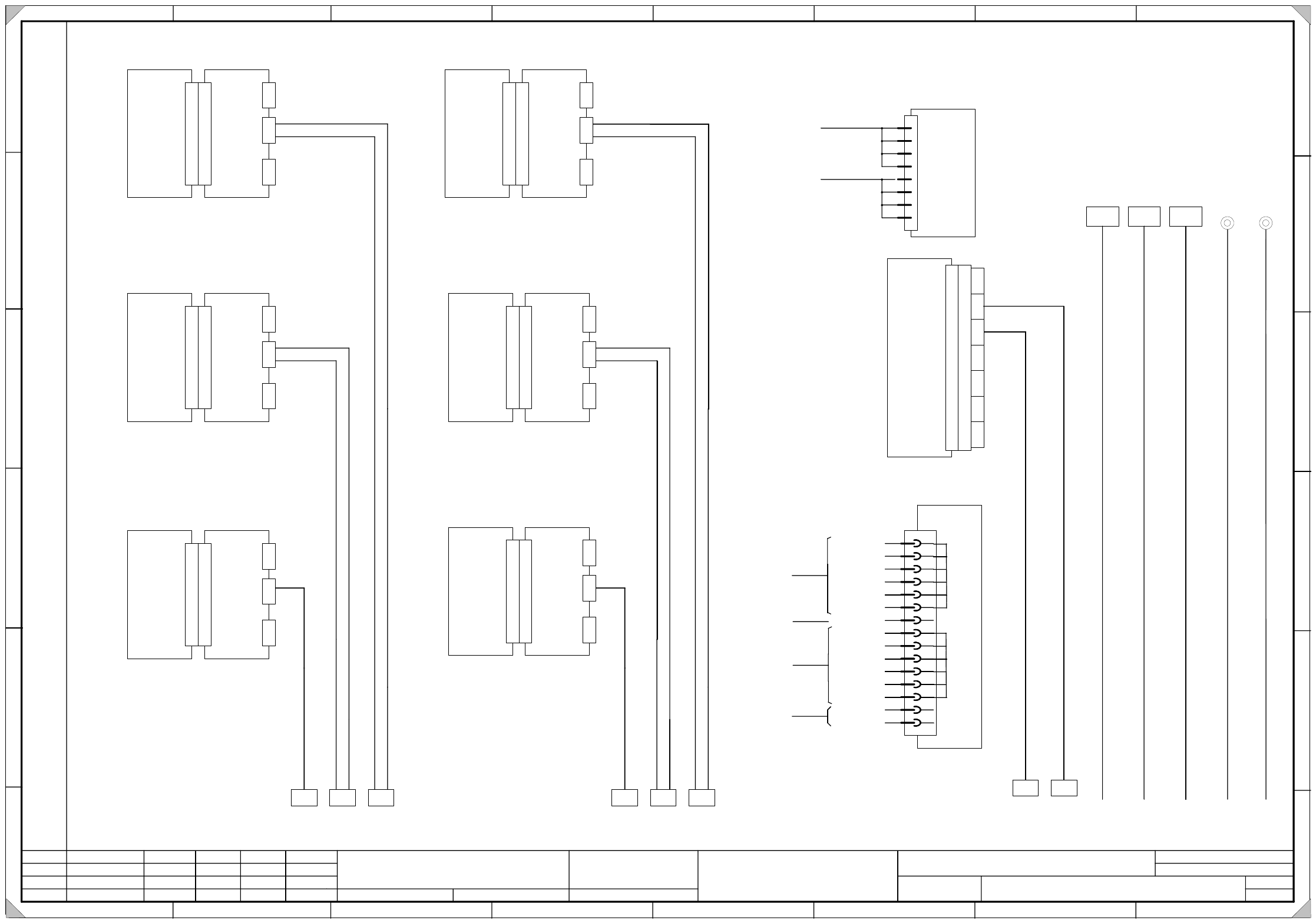
1 - 26
00354475-010101LD3 Servo unit, S-27 HM, overview (sh. 1 of 2)
1.
1.
25.05.2000
25.05.2000
Tuth
Tuth 04.05.2001
Tuth
Siplace S27 HM SMD Placement System
Servo unit, overview
00354475-010101LD3
25.05.2000 Tuth
1.
SIEMENS AG
L&A EA
Status Modified Date Name Standard Orig. Repl.f. Repl. by
Document status
Product status
Function status Date
Author
Check.
Sheet
Sh.
W
e
i
t
e
r
g
a
b
e
s
o
w
i
e
V
e
r
v
i
e
l
f
ä
l
t
i
g
u
n
g
d
i
e
s
e
r
U
n
t
e
r
l
a
g
e
,
V
e
r
-
w
e
r
t
u
n
g
u
n
d
M
i
t
t
e
i
l
u
n
g
i
h
r
e
s
I
n
h
a
l
t
s
n
i
c
h
t
g
e
s
t
a
t
t
e
t
,
s
o
w
e
i
t
n
i
c
h
t
a
u
s
d
r
ü
c
k
l
i
c
h
z
u
g
e
s
t
a
n
d
e
n
.
Z
u
w
i
d
e
r
h
a
n
d
l
u
n
g
e
n
v
e
r
-
p
f
l
i
c
h
t
e
n
z
u
S
c
h
a
d
e
n
e
r
s
a
t
z
.
A
l
l
e
R
e
c
h
t
e
v
o
r
b
e
h
a
l
t
e
n
,
i
n
s
b
e
s
o
n
d
e
r
e
f
ü
r
d
e
n
F
a
l
l
d
e
r
P
a
t
e
n
t
e
r
t
e
i
l
u
n
g
o
d
e
r
G
M
-
E
i
n
t
r
a
g
u
n
g
P
r
o
p
r
i
e
t
a
r
y
d
a
t
e
,
c
o
m
p
a
n
y
c
o
n
f
i
d
e
n
t
i
a
l
.
A
l
l
r
i
g
h
t
s
r
e
s
e
r
v
d
.
C
o
n
f
i
e
a
t
i
t
r
e
d
e
s
e
c
r
e
t
d
´
e
n
t
r
e
p
r
i
s
e
.
T
o
u
s
d
r
o
i
t
s
r
e
s
e
r
v
e
s
.
C
o
m
u
n
i
c
a
d
o
c
o
m
o
s
e
g
r
e
d
o
e
m
p
r
e
s
a
r
i
a
l
.
R
e
s
e
r
v
a
d
o
s
t
o
d
o
s
o
s
d
i
r
e
i
l
o
s
.
C
o
n
f
i
a
d
o
c
o
m
o
s
e
c
r
e
t
e
i
n
d
u
s
t
r
i
a
l
.
N
o
s
r
e
s
e
r
v
a
m
o
s
t
o
d
o
s
l
o
s
d
e
r
e
c
h
o
s
.
A
B
C
D
E
F
1 2 3 4 5 6 7 8
1
2 3 4 5 6 7 8
A
B
C
D
E
F
0
0
3
2
1
5
3
9
-
x
x
0
0
3
2
1
5
4
1
-
x
x
(
W
1
)
0
0
3
2
1
5
4
4
-
x
x
(
W
1
)
0
0
3
2
1
5
4
1
-
x
x
(
W
2
)
0
0
3
2
1
5
4
4
-
x
x
(
W
2
)
X30aaX29aaX28aa
0
0
3
2
1
5
6
5
-
x
x
0
0
3
2
1
5
6
7
-
x
x
(
W
1
)
0
0
3
2
1
5
6
9
-
x
x
(
W
1
)
0
0
3
2
1
5
6
7
-
x
x
(
W
2
)
0
0
3
2
1
5
6
9
-
x
x
(
W
2
)
X30baX29baX28ba
X34aa X34ba
0
0
3
2
1
5
7
1
-
x
x
0
0
3
2
1
5
4
7
-
x
x
X2 X3 X4
0
0
3
0
0
1
6
3
-
x
x
0
0
3
0
0
1
6
4
-
x
x
0
0
3
0
0
1
8
2
-
x
x
B
a
l
l
a
s
t
c
i
r
c
u
i
t
X13
A16
a2
a4
a6
a8
Star point 007 1L-
c2
c4
c6
c8
Star point 009 1L+
S
e
r
v
o
c
o
n
t
r
o
l
l
e
r
d
p
1
-
a
x
i
s
(
G
a
n
t
r
y
1
)
B
a
c
k
p
l
a
n
e
d
p
1
-
a
x
i
s
(
G
a
n
t
r
y
1
)
X
1
X
1
v
f
SP head
A3 A20
X
4
v
f
X
3
v
f
X
2
v
f
(vf)
S
e
r
v
o
c
o
n
t
r
o
l
l
e
r
z
-
a
x
i
s
(
G
a
n
t
r
y
1
)
B
a
c
k
p
l
a
n
e
z
-
a
x
i
s
(
G
a
n
t
r
y
1
)
X
1
X
1
v
d
SP head
A4 A21
X
4
v
d
X
3
v
d
X
2
v
d
(vd)
S
e
r
v
o
c
o
n
t
r
o
l
l
e
r
S
t
a
r
-
a
x
i
s
(
G
a
n
t
r
y
1
)
B
a
c
k
p
l
a
n
e
S
t
a
r
a
x
i
s
(
G
a
n
t
r
y
1
)
X
1
X
1
v
c
SP head
A5 A22
X
4
v
c
X
3
v
c
X
2
v
c
(vc)
S
e
r
v
o
c
o
n
t
r
o
l
l
e
r
d
p
1
-
a
x
i
s
(
G
a
n
t
r
y
2
)
B
a
c
k
p
l
a
n
e
d
p
1
-
a
x
i
s
(
G
a
n
t
r
y
2
)
X
1
X
1
v
r
SP head
A8 A25
X
4
v
r
X
3
v
r
X
2
v
r
(vr)
S
e
r
v
o
c
o
n
t
r
o
l
l
e
r
z
-
a
x
i
s
(
G
a
n
t
r
y
2
)
B
a
c
k
p
l
a
n
e
z
-
a
x
i
s
(
G
a
n
t
r
y
2
)
X
1
X
1
v
p
SP head
A9 A26
X
4
v
p
X
3
v
p
X
2
v
p
(vp)
S
e
r
v
o
c
o
n
t
r
o
l
l
e
r
S
t
a
r
a
x
i
s
(
G
a
n
t
r
y
2
)
B
a
c
k
p
l
a
n
e
S
t
a
r
a
x
i
s
(
G
a
n
t
r
y
2
)
X
1
X
1
v
o
SP head
A10 A27
X
4
v
o
X
3
v
o
X
2
v
o
(vo)
1
2
C
r
a
s
h
b
o
a
r
d
X
1
A15
X
1
1
X
1
1
b
X
1
1
a
X
1
1
c
X
1
1
d
X
1
1
e
X
1
1
f
X
1
1
g
P
o
w
e
r
s
u
p
p
l
y
u
n
i
t
+
/
-
1
5
V
A17
1L-
4
6
8
10
12
14
16
18
20
22
24
26
28
30
32
6L+
-15V
-15V
-15V
-15V
-15V
-15V
1L-
+15V
+15V
+15V
+15V
+15V
+15V
Input
Output
X12
Output
Input
0
0
3
2
4
3
5
9
-
x
x
To terminal panels
S
t
a
r
p
o
i
n
t
0
0
7
1
L
-
G
r
o
u
n
d
0
0
3
2
1
5
8
2
-
x
x
G
r
o
u
n
d
b
o
l
t
R
i
g
h
t
s
i
d
e
p
a
n
e
l
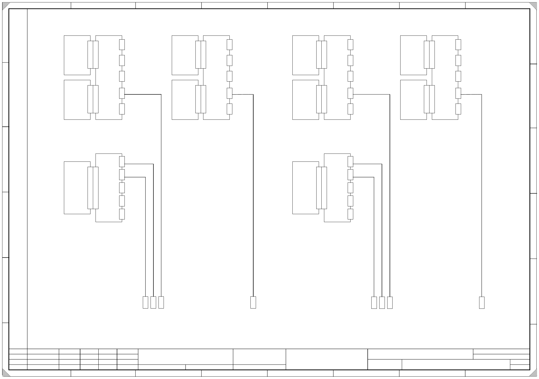
1 - 27
00354475-010101LD3 Servo unit, S-27 HM, overview (sh. 2 of 2)
1.
1.
25.05.2000
25.05.2000
Tuth
Tuth 04.05.2001
Tuth
Siplace S27 HM SMD Placement System
Servo unit, overview
00354475-010101LD3
25.05.2000 Tuth
1.
SIEMENS AG
L&A EA
Status Modified Date Name Standard Orig. Repl.f. Repl. by
Document status
Product status
Function status Date
Author
Check.
Sheet
Sh.
W
e
i
t
e
r
g
a
b
e
s
o
w
i
e
V
e
r
v
i
e
l
f
ä
l
t
i
g
u
n
g
d
i
e
s
e
r
U
n
t
e
r
l
a
g
e
,
V
e
r
-
w
e
r
t
u
n
g
u
n
d
M
i
t
t
e
i
l
u
n
g
i
h
r
e
s
I
n
h
a
l
t
s
n
i
c
h
t
g
e
s
t
a
t
t
e
t
,
s
o
w
e
i
t
n
i
c
h
t
a
u
s
d
r
ü
c
k
l
i
c
h
z
u
g
e
s
t
a
n
d
e
n
.
Z
u
w
i
d
e
r
h
a
n
d
l
u
n
g
e
n
v
e
r
-
p
f
l
i
c
h
t
e
n
z
u
S
c
h
a
d
e
n
e
r
s
a
t
z
.
A
l
l
e
R
e
c
h
t
e
v
o
r
b
e
h
a
l
t
e
n
,
i
n
s
b
e
s
o
n
d
e
r
e
f
ü
r
d
e
n
F
a
l
l
d
e
r
P
a
t
e
n
t
e
r
t
e
i
l
u
n
g
o
d
e
r
G
M
-
E
i
n
t
r
a
g
u
n
g
P
r
o
p
r
i
e
t
a
r
y
d
a
t
e
,
c
o
m
p
a
n
y
c
o
n
f
i
d
e
n
t
i
a
l
.
A
l
l
r
i
g
h
t
s
r
e
s
e
r
v
d
.
C
o
n
f
i
e
a
t
i
t
r
e
d
e
s
e
c
r
e
t
d
´
e
n
t
r
e
p
r
i
s
e
.
T
o
u
s
d
r
o
i
t
s
r
e
s
e
r
v
e
s
.
C
o
m
u
n
i
c
a
d
o
c
o
m
o
s
e
g
r
e
d
o
e
m
p
r
e
s
a
r
i
a
l
.
R
e
s
e
r
v
a
d
o
s
t
o
d
o
s
o
s
d
i
r
e
i
l
o
s
.
C
o
n
f
i
a
d
o
c
o
m
o
s
e
c
r
e
t
e
i
n
d
u
s
t
r
i
a
l
.
N
o
s
r
e
s
e
r
v
a
m
o
s
t
o
d
o
s
l
o
s
d
e
r
e
c
h
o
s
.
A
B
C
D
E
F
1 2 3 4 5 6 7 8
1
2 3 4 5 6 7 8
A
B
C
D
E
F
D
y
n
.
b
r
a
k
e
X
-
a
x
i
s
(
G
a
n
t
r
y
1
)
B
a
c
k
p
l
a
n
e
X
-
a
x
i
s
(
G
a
n
t
r
y
1
)
X
2
v
a
SP head
A11 A18
X
5
v
a
X
4
v
a
X
3
v
a
1L+ / GND
S
e
r
v
o
c
o
n
t
r
o
l
l
e
r
X
-
a
x
i
s
(
G
a
n
t
r
y
1
)
X
1
v
a
SP head
A1
X
1
v
a
X
2
v
a
X
7
v
a
X
6
v
a
Motor
+ / -15V
Anti-crash board
Nom. value
Tachometer
(va)
D
y
n
.
b
r
a
k
e
X
-
a
x
i
s
(
G
a
n
t
r
y
2
)
B
a
c
k
p
l
a
n
e
X
-
a
x
i
s
(
G
a
n
t
r
y
2
)
X
2
v
m
SP head
A13 A23
X
5
v
m
X
4
v
m
X
3
v
m
1L+ / GND
S
e
r
v
o
c
o
n
t
r
o
l
l
e
r
X
-
a
x
i
s
(
G
a
n
t
r
y
2
)
X
1
v
m
SP head
A2
X
1
v
m
X
2
v
m
X
7
v
m
X
6
v
m
Motor
+ / -15V
Anti-crash board
Nom. value
Tachometer
(vm)
D
y
n
.
b
r
a
k
e
Y
-
a
x
i
s
(
G
a
n
t
r
y
2
)
B
a
c
k
p
l
a
n
e
Y
-
a
x
i
s
(
G
a
n
t
r
y
2
)
X
2
v
n
SP head
A14 A24
X
5
v
n
X
4
v
n
X
3
v
n
1L+ / GND
S
e
r
v
o
c
o
n
t
r
o
l
l
e
r
Y
-
a
x
i
s
(
G
a
n
t
r
y
2
)
X
1
v
n
SP head
A7
X
1
v
n
X
2
v
n
X
7
v
n
X
6
v
n
Motor
+ / -15V
Anti-crash board
Nom. value
Tachometer
(vn)
D
y
n
.
b
r
a
k
e
Y
-
a
x
i
s
(
G
a
n
t
r
y
1
)
B
a
c
k
p
l
a
n
e
Y
-
a
x
i
s
(
G
a
n
t
r
y
1
)
X
2
v
b
SP head
A12 A19
X
5
v
b
X
4
v
b
X
3
v
b
1L+ / GND
S
e
r
v
o
c
o
n
t
r
o
l
l
e
r
Y
-
a
x
i
s
(
G
a
n
t
r
y
1
)
X
1
v
b
SP head
A6
X
1
v
b
X
2
v
b
X
7
v
b
X
6
v
b
Motor
+ / -15V
Anti-crash board
Nom. value
Tachometer
(vb)
T
a
c
h
o
m
e
t
e
r
a
n
a
l
y
s
i
s
X
/
Y
-
a
x
e
s
(
G
a
n
t
r
y
1
)
B
a
c
k
p
l
a
n
e
T
a
c
h
o
m
e
t
e
r
a
n
a
l
y
s
i
s
(
G
a
n
t
r
y
1
)
X
1
X
1
v
e
A31
A29
X
4
v
e
X
3
v
e
X
2
v
e
X
5
v
e
X
6
v
e
tachometer
+ / -15V
RLG-Y
X-tachometer
Y-tachometer
(ve)
tachometer
RLG-X
T
a
c
h
o
m
e
t
e
r
a
n
a
l
y
s
i
s
X
/
Y
-
a
x
e
s
(
G
a
n
t
r
y
2
)
B
a
c
k
p
l
a
n
e
T
a
c
h
o
a
u
s
w
e
r
t
u
n
g
(
P
o
r
t
a
l
2
)
X
1
X
1
v
s
A32
A30
X
4
v
s
X
3
v
s
X
2
v
s
X
5
v
s
X
6
v
s
tachometer
+ / -15V
RLG-Y
X-tachometer
tachometer
RLG-X
Y-tachometer
(vs)
X
3
2
a
X
3
8
a
a
X
3
6
a
a
X
3
1
a
X
3
2
b
X
3
8
b
a
X
3
6
b
a
X
3
1
b
0
0
3
5
4
4
7
1
-
x
x
0
0
3
5
4
4
7
3
-
x
x
0
0
3
5
4
4
1
9
-
x
x
0
0
3
5
4
4
1
7
-
x
x
0
0
3
5
4
4
7
2
-
x
x
0
0
3
5
4
4
7
4
-
x
x
0
0
3
5
4
4
2
0
-
x
x
0
0
3
5
4
4
1
8
-
x
x
2
2
Please note !
Insert jumpers J1 and J2 on the backplane for the tachometer analysis of gantry 2 ( A30 vs).
(This way, the sense of rotation and the tachometer voltage is adjusted.)
Insert jumper J1 on the backplanes for the Y-axes of gantry 1 and gantry 2 (A19 vb and A24 vn).
(This way, monitoring of the motor temperature is disabled.)
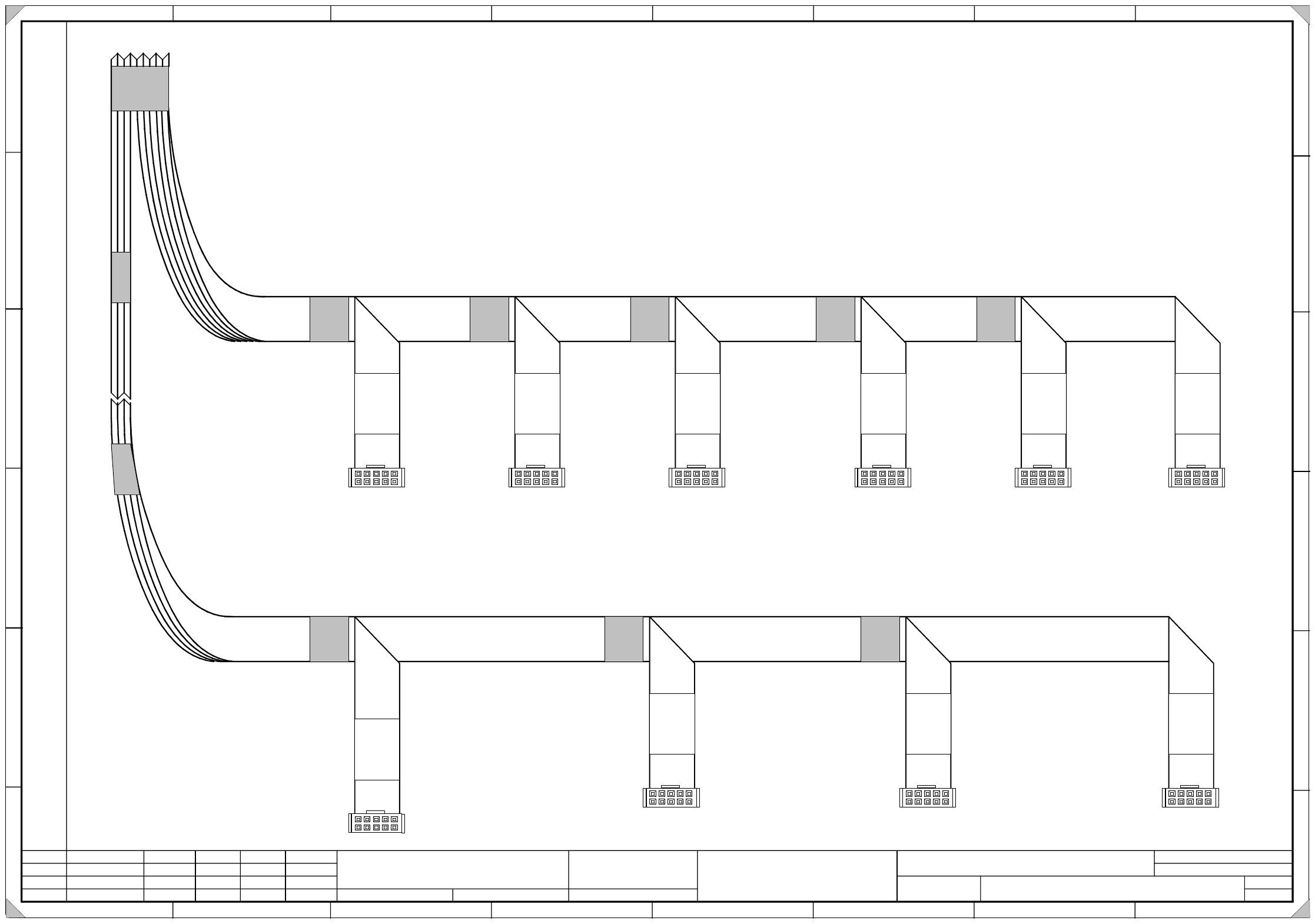
1 - 28
00364153-010201FD3 Control unit, cable harness (sh. 1 of 3)
1.
1.
30.10.2001
15.04.2001
Tuth
Tuth 15.04.2001
Tuth
Siplace S27 HM Placement System
Control unit, cable harness
00364153-010201FD3
15.04.2001 Tuth
2.
SIEMENS
L&A EA
Status Modified Date Name Stand. Orig. Repl.f. Repl. by
Document status
Product status
Function status Date
Suthor
Check.
Sheet
Sh.
W
e
i
t
e
r
g
a
b
e
s
o
w
i
e
V
e
r
v
i
e
l
f
ä
l
t
i
g
u
n
g
d
i
e
s
e
r
U
n
t
e
r
l
a
g
e
,
V
e
r
-
w
e
r
t
u
n
g
u
n
d
M
i
t
t
e
i
l
u
n
g
i
h
r
e
s
I
n
h
a
l
t
s
n
i
c
h
t
g
e
s
t
a
t
t
e
t
,
s
o
w
e
i
t
n
i
c
h
t
a
u
s
d
r
ü
c
k
l
i
c
h
z
u
g
e
s
t
a
n
d
e
n
.
Z
u
w
i
d
e
r
h
a
n
d
l
u
n
g
e
n
v
e
r
-
p
f
l
i
c
h
t
e
n
z
u
S
c
h
a
d
e
n
e
r
s
a
t
z
.
A
l
l
e
R
e
c
h
t
e
v
o
r
b
e
h
a
l
t
e
n
,
i
n
s
b
e
s
o
n
d
e
r
e
f
ü
r
d
e
n
F
a
l
l
d
e
r
P
a
t
e
n
t
e
r
t
e
i
l
u
n
g
o
d
e
r
G
M
-
E
i
n
t
r
a
g
u
n
g
P
r
o
p
r
i
e
t
a
r
y
d
a
t
e
,
c
o
m
p
a
n
y
c
o
n
f
i
d
e
n
t
i
a
l
.
A
l
l
r
i
g
h
t
s
r
e
s
e
r
v
d
.
C
o
n
f
i
e
a
t
i
t
r
e
d
e
s
e
c
r
e
t
d
´
e
n
t
r
e
p
r
i
s
e
.
T
o
u
s
d
r
o
i
t
s
r
e
s
e
r
v
e
s
.
C
o
m
u
n
i
c
a
d
o
c
o
m
o
s
e
g
r
e
d
o
e
m
p
r
e
s
a
r
i
a
l
.
R
e
s
e
r
v
a
d
o
s
t
o
d
o
s
o
s
d
i
r
e
i
l
o
s
.
C
o
n
f
i
a
d
o
c
o
m
o
s
e
c
r
e
t
e
i
n
d
u
s
t
r
i
a
l
.
N
o
s
r
e
s
e
r
v
a
m
o
s
t
o
d
o
s
l
o
s
d
e
r
e
c
h
o
s
.
A
B
C
D
E
F
1 2 3 4 5 6 7 8
1
2 3 4 5 6 7 8
A
B
C
D
E
F
S
i
e
m
e
n
s
P
L
E
A
X
2
v
a
0
0
3
6
4
1
3
1
-
x
x
S
i
e
m
e
n
s
P
L
E
A
X
2
v
b
0
0
3
6
4
1
3
2
-
x
x
S
i
e
m
e
n
s
P
L
E
A
X
2
v
m
0
0
3
6
4
1
3
8
-
x
x
S
i
e
m
e
n
s
P
L
E
A
X
2
v
n
0
0
3
6
4
1
3
9
-
x
x
S
i
e
m
e
n
s
P
L
E
A
X
2
v
f
0
0
3
6
4
1
3
7
-
x
x
S
i
e
m
e
n
s
P
L
E
A
X
2
v
d
0
0
3
6
4
1
3
6
-
x
x
S
i
e
m
e
n
s
P
L
E
A
X
2
v
c
0
0
3
6
4
1
3
5
-
x
x
S
i
e
m
e
n
s
P
L
E
A
X
2
v
o
0
0
3
6
4
1
4
0
-
x
x
S
i
e
m
e
n
s
P
L
E
A
X
2
v
p
0
0
3
6
4
1
5
1
-
x
x
S
i
e
m
e
n
s
P
L
E
A
X
2
v
r
0
0
3
6
4
1
5
2
-
x
x
1
3
Detail: Nom. value cable to servo