S27HM Circuit Diagrams.pdf - 第47页
2 - ii SIPLACE S -27 HM Detail ed Circuit Diagrams Folder 05/2005 US Editi on convers ion bo ard "tr ansporta tion chee k C" ( sh. 9 of 11) 2 - 31 LPT10-0 20101LD 3 PCB si ngle con veyo r / PCB du al co nveyor …

SIPLACE S-27 HM Detailed Circuit Diagrams Folder
05/2005 US Edition
2 - i
2 Detailed Circuit Diagrams
NH01-020101LD3 EMERGENCY-STOP circuit with power supply 00336812-xx
or 00356395-xx (Japan version) 2 - 1
NH01-020101LD3 EMERGENCY-STOP circuit - signaling circuit with power supply 00336812-xx
or 00356395-xx (Japan version) 2 - 2
NH02-010101LD3 EMERGENCY-STOP circuit with power supply 00375503-xx 2 - 3
NH02-010101LD3 EMERGENCY-STOP circuit - signaling circuit with power supply 00375503-xx 2 - 4
NH03-010101LD3 EMERGENCY-STOP circuit with power supply 00375539-xx (Japan version) 2 - 5
NH03-010101LD3 EMERGENCY-STOP circuit - signaling circuit with power supply 00375539-xx
(Japan version) 2 - 6
X01-010101LD3 X-axis, gantry 1 2 - 7
X02-010101LD3 X-axis, gantry 2 2 - 8
Y01-010101LD3 Y-axis, gantry 1 2 - 9
Y02-010101LD3 Y-axis, gantry 2 2 - 10
DR01-010101LD3 Collect&Place head - star axis, gantry 1 2 - 11
DR02-010101LD3 Collect&Place head - star axis, gantry 2 2 - 12
Z01-010101LD3 Collect&Place head - Z-axis, gantry 1 2 - 13
Z02-010101LD3 Collect&Place head - Z-axis, gantry 2 2 - 14
DP01-010101LD3 Collect&Place head - DP-axis, gantry 1 2 - 15
DP02-010101LD3 Collect&Place head - DP-axis, gantry 2 2 - 16
ZM01-010101LD3 Collect&Place head - adjustment drive motors - forced air valve,
CAN bus, gantry 1 2 - 17
ZM02-010101LD3 Collect&Place head - adjustment drive motors - forced air valve,
CAN bus, gantry 2 2 - 18
SV_STEU01-020101LD3 Power supply - control unit, terminal panel - conversion board, gantry 2 - 19
SV_SV01-020101LD3 Voltage supply for servo amplifier and anti-crash board with
power supply unit 00336812-xx/00356395-xx (sh. 1 of 3) 2 - 20
SV_SV01-020101LD3 Voltage supply for servo amplifier and anti-crash board with
power supply unit 00375503-xx/00375539-xx (sh. 2 of 3) 2 - 21
SV_SV01-020101LD3 Voltage supply for servo amplifier and anti-crash board (sh. 3 of 3) 2 - 22
LPT01-020101LD3 PCB single conveyor / PCB dual conveyor,
conveyor control TSP-201 (sh. 1 of 11) 2 - 23
LPT02-020101LD3 PCB single conveyor / PCB dual conveyor,
conveyor control TSP-201 (sh. 2 of 11) 2 - 24
LPT03-020101LD3 PCB single conveyor / PCB dual conveyor,
conversion board "conveyor"(sh. 3 of 11) 2 - 25
LPT04-020101LD3 PCB single conveyor / PCB dual conveyor,
conversion board "conveyor"(sh. 4 of 11) 2 - 26
LPT05-020101LD3 PCB single conveyor / PCB dual conveyor,
conversion board "conveyor"(sh. 5 of 11) 2 - 27
LPT06-020101LD3 PCB single conveyor / PCB dual conveyor,
conversion board "conveyor"(sh. 6 of 11) 2 - 28
LPT07-020101LD3 PCB single conveyor / PCB dual conveyor,
conversion board "transportation cheek A" (sh. 7 of 11) 2 - 29
LPT08-020101LD3 PCB single conveyor / PCB dual conveyor,
conversion board "transportation cheek B" (sh. 8 of 11) 2 - 30
LPT09-020101LD3 PCB single conveyor / PCB dual conveyor,

2 - ii
SIPLACE S-27 HM Detailed Circuit Diagrams Folder
05/2005 US Edition
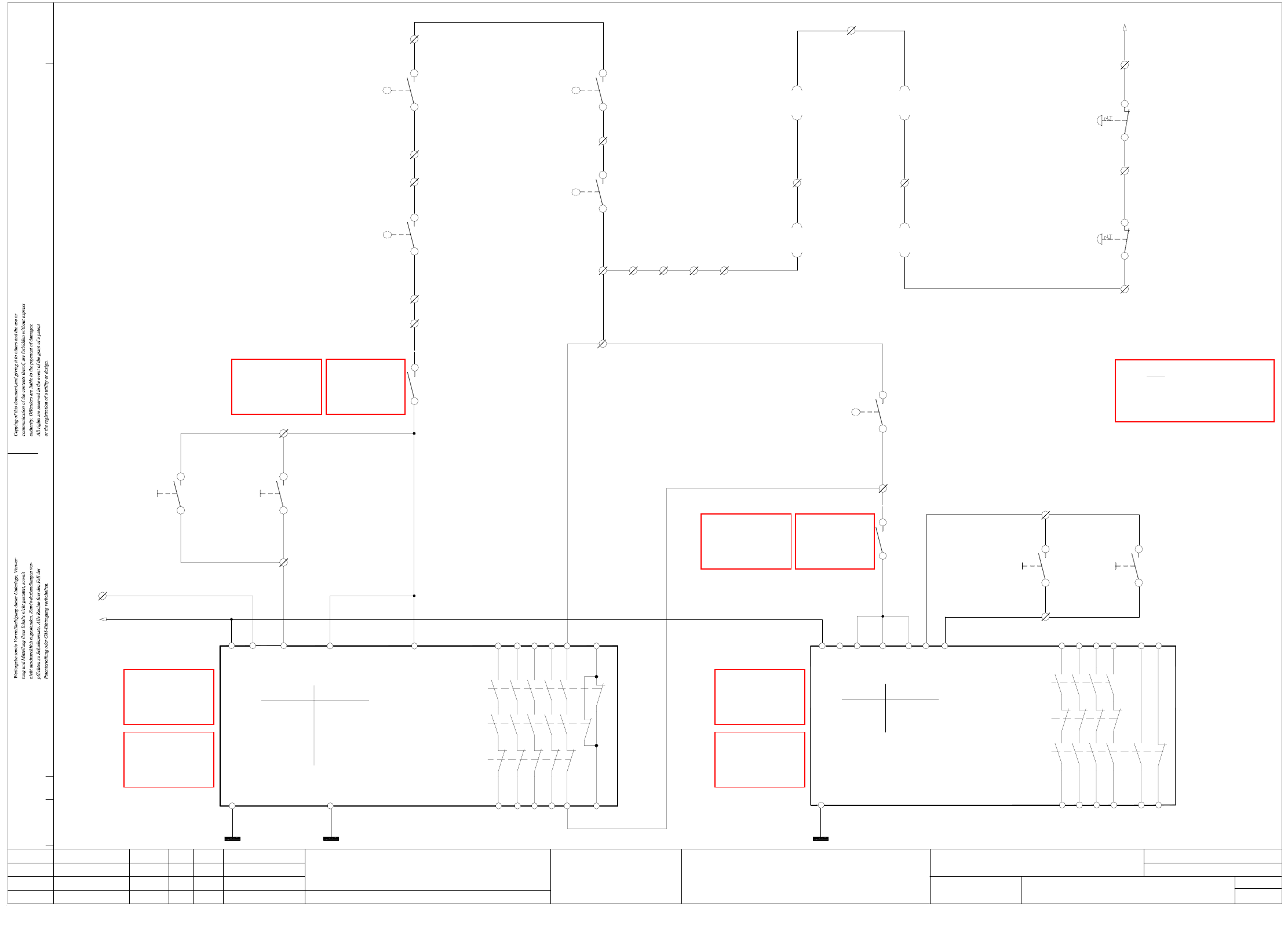
conversion board "transportation cheek C" (sh. 9 of 11) 2 - 31
LPT10-020101LD3 PCB single conveyor / PCB dual conveyor,
conversion board "transportation cheek D" (sh. 10 of 11) 2 - 32
LPT11-020101LD3 PCB single conveyor / PCB dual conveyor,
conversion board "lifting table", track 1 + track 2 (sh. 11 of 11) 2 - 33
BT01-010101LD3 Component table, mobile, righthand side 2 - 34
BT01-010101LD3 Component table, mobile, lefthand side 2 - 35
GS01-010201LD3 Tape cutter, pneumatically operated, righthand side 2 - 36
GS02-010201LD3 Tape cutter, pneumatically operated, lefthand side 2 - 37
PW01-010101LD3 Nozzle changer 2 - 38
MTC01-010201LD3 MTC interface, righthand side 2 - 39
MTC02-010201LD3 MTC interface, lefthand side 2 - 40
2 - 1
2 Detailed Circuit Diagrams
NH01-020101LD3 EMERGENCY-STOP circuit with power supply 00336812-xx
or 00356395-xx (Japan version)
00322070-xx br
00322112-xx ye
00322112-xx gn
Component table,
MTC interface,
00321436-xx br
00321436-xx wh
00321433-xx br
00321433-xx wh
push-button
push-button
00321529-xx S1
00321528-xx S1
X211/4
2
1
X211/3
2
1
X211/2
3c 00322105-xx/X57b
4c 00322105-xx/X57b
X211/6
1a 00322064-xx/X37b
2c 00322064-xx/X37b
NH01_SH01.DWG
Stromlaufplan/Circuit diagram
SMD Placement System SIPLACE S-27 HM
1
2
EMERGENY-STOP circuit
with power supply 00336812-xx or
X211/7
Output conveyor
Input conveyor
EMERG.-STOP
EMERG.-STOP
Sh.
Sheet
righthand side
righthand side
2c 00322063-xx/X3ta
1a 00322063-xx/X3ta
Component table,
lefthand side
00322069-xx br
00322069-xx bl
X211/5
00322111-xx gn
4c 00322104-xx/X57a
3c 00322104-xx/X57a
00322111-xx ye
lefthand side
MTC interface,
DateStatus Name Stand. Orig./Repl.f/Replaced by
Author
Check.
Date
Mat. no.:
CAD file:
Modified
2.
1.
1.
02.05.05
02.11.02
02.11.02 Hi
Hi
Hi 02.05.2005
Hi
L&A EA
SIEMENS
NH01-020101LD3
Doc. status
Product status
Function status
00356395-xx (version for Japan)
ReleaseH2+H3
Channel 1H3
Power
Channel 2
Display
H1
H2
LED
00321113-xx wh & bn
Fuse F10:2
24V AC
24V AC
00336812-xx K1
WARNING: If you install the option remove
jumpers X211/ 25-26, 26-27, 27-28 and 28-29.
Connecting terminals for feeder crash sensors
OPTION: X211/ 25,26,27,28,29
X211/29 262728
00321113-xx ye
4
3
3TK2805
unit
Safety protection
Monitoring
software release signal
for machine 'ON'
00353088-xx
OPTION: Cover switch, preceding machine (00321421-xx)
Connect cable 00305816-xx to X211/11 gn - X211/12 ye
WARNING: If you install the option
remove jumper X211/11 - X211/12.
remove jumper X211/13 - X211/14.
WARNING: If you install the option
Connect cable 00305817-xx to X211/13 gn - X211/14 ye
OPTION: Cover switch, succeeding machine (00321421-xx)
ONON
conveyor conveyor
65
43
23 33
5313
K3'
X5
K2'
K1'
X3X4X1A1
66
44
24
34
54
14
X6
A2
00321416-xx S1
righthand side
lefthand side
00321417-xx S1
Protective cover
switch
switch
Protective cover
Protective cover
switch
Input conveyor
00303614-xx S1
00321574-xx ye
00321574-xx gn
00321573-xx ye
00321573-xx gn
00305815-xx gn
00305815-xx ye
22
21
22
21
X211/9
X211/11
22
21
X211/10
Protective cover
switch
00303617-xx S1
Output conveyor
X211/12
21
22
X211/13
X211/14
00305818-xx gn
00305818-xx ye
13
14
00321113-xx bl
00321529-xx S2
X211/17
X211/16
4
3
00321528-xx S2
push-button
output
push-button
input
00321113-xx gn
00321434-xx gr
00321434-xx pk
00321432-xx gr
00321432-xx pk
Note:
X211 terminal strip (I/O distributor)
Ready
Release
Display
H1
H2
LED
X211/8
00321529-xx S4
conveyorconveyor
push-button push-button
65
66
57
4323
13
33
X6
X4 X5
K1'
K2'
K3'
X3X2X1A1
58
44
24
14 34
A2
ON
output
00321529-xx S2
input
ON
00321528-xx S2
43
44
X211/18
X211/19
00321113-xx grpk
00321434-xx gn
00321434-xx ye
3
4
3
4
00321432-xx gn
00321432-xx ye
00321113-xx rdbl
Key-operated
switch
X211/15
3
4
00321113-xx vio
00321434-xx whye
00321434-xx brgn
00321113-xx bk
25
00322070-xx bl
X211/2
K1 K2
00321113-xx wh & bn
24V AC
K1:X1
00336812-xx K3
00356395-xx K1
3TK2805
Safety protection
unit
00356395-xx K2
3TK2804
Safety protection
Safety protection
00336812-xx K2
3TK2804
for machine 'ON'
software release signal
Monitoring
00356395-xx K3
00356395-xx K3
Monitoring
software release signal
for machine 'ON'
00336812-xx K3
for machine 'ON'
software release signal
Monitoring
See page 4-2
See page 4-12
See page 4-2
See page 4-12
See page 4-2
See page 4-12
See page 4-2
See page 4-12
See page 4-4