S27HM Circuit Diagrams.pdf - 第51页
2 - 4 NH02-0 10101 LD3 EME RGENCY -STOP circ uit - si gnaling circuit w ith po wer sup ply 0037 5503- xx Off but ton 00321432 -xx vi 00321432 -xx bk Key-operate d switch 00321434- xx bk 00321434 -xx vi 003214 34- xx g rp…

2 - 3
NH02-010101LD3 EMERGENCY-STOP circuit with power supply 00375503-xx
K11
A2
A1
Y44
Y33
Y22Y21
K1
Y43
Y11Y10 Y12
PE 14
Y34 13
K12
31
24
K11
24
13
34 42 52
4133 51
13
K3
14
X211/8
00321529-xx S4
Key-operated switch
X211/15
3
4
00321434-xx whye
00321434-xx bngn
25
00322070-xx bl
00321113-xx wh & bn
24V AC
K3:14
3TK2825
A2
A1
GND
3RT1015
3RT1015
24
23
K12
A1
A2
lefthand side
00322069-xx bn
00322069-xx bl
X211/5
00322111-xx gn
4c 00322104-xx/X57a
3c 00322104-xx/X57a
00322111-xx ye
lefthand side
MTC interface,
DateStatus Name Stand. Orig./Repl.f/Replaced by
Author
Check.
Date
Mat. no.:
CAD file:
Modified
1.
1.
1.
30.05.05
30.05.05
30.05.05 Hi
Hi
Hi 30.05.2005
Hi
L&A EA
SIEMENS
NH02-010101LD3
Doc. status
Product status
Function status
WARNING: If you install the option remove
jumpers X211/ 25-26, 26-27, 27-28 and 28-29.
Connecting terminals for feeder crash sensors
OPTION: X211/ 25,26,27,28,29
X211/29
262728
00321113-xx gn
3
4
00353088-xx
OPTION: Cover switch, preceding machine (00321421-xx)
Connect cable 00305816-xx to X211/11 gn - X211/12 ye
WARNING: If you install the option
remove jumper X211/11 - X211/12.
remove jumper X211/13 - X211/14.
WARNING: If you install the option
Connect cable 00305817-xx to X211/13 gn - X211/14 ye
OPTION: Cover switch, succeeding machine (00321421-xx)
ONON
conveyor conveyor
00321416-xx S1
righthand side
lefthand side
00321417-xx S1
Protective cover
switch
switch
Protective cover
Protective cover
switch
Input conveyor
00303614-xx S1
00321574-xx ye
00321574-xx gn
00321573-xx ye
00321573-xx gn
00305815-xx gn
00305815-xx ye
22
21
22
21
X211/9
X211/11
22
21
X211/10
Protective cover
switch
00303617-xx S1
Output conveyor
X211/12
21
22
X211/13
X211/14
00305818-xx gn
00305818-xx ye
00321113-xx bl
00321529-xx S2
X211/16
X211/17
3
4
00321528-xx S2
push-button
output
push-button
input
00321113-xx ye
00321434-xx pk
00321434-xx gy
00321432-xx pk
00321432-xx gy
Note:
X211 terminal strip (I/O distributor)
00322070-xx bn
00322112-xx ye
00322112-xx gn
Component table,
MTC interface,
00321436-xx bn
00321436-xx wh
00321433-xx bn
00321433-xx wh
push-button
push-button
00321529-xx S1
00321528-xx S1
X211/4
2
1
X211/3
2
1
X211/2
3c 00322105-xx/X57b
4c 00322105-xx/X57b
X211/6
1a 00322064-xx/X37b
2c 00322064-xx/X37b
NH02_SH01.DWG
Stromlaufplan/Circuit diagram
SMD Placement System SIPLACE S-27 HM
1
2
EMERGENY-STOP circuit
with power supply 00375503-xx
X211/7
Output conveyor
Input conveyor
EMERG.-STOP
EMERG.-STOP
Sh.
Sheet
righthand side
righthand side
2c 00322063-xx/X3ta
1a 00322063-xx/X3ta
Component table,
14
MP1 M
215
226
226
215
K2
3RT1015
A2
A1
246
135
14
13
22
21
A2(-)
A1(+)
K3
K2
44
13
K3
43
T2
T1
2
1
15
14
24VAC
Fuse F10:2
bk
bk
bn
wh
00321113-xx
X211/2
00375503-xx
00321434-xx ye
X211/19
00321113-xx rdbl
00321432-xx ye
X211/18
conveyor
push-button
00321529-xx S2
ON
output
00321113-xx gypk
00321434-xx gn
3
4
00321432-xx gn
conveyor
push-button
input
00321528-xx S2
ON
3
4
00375503-020101LD3
X212:4
00321113-xx
whye
X211:11
whpk
00321113-xx
rd
00321113-xx
00321113-xx
pk
X212:12
00321113-xx
X211:22
yebn
X1kb:1
00321113-xx
whgy
X4ka -
00321113-xx
pkbn
gybn
00321113-xx
X2ka:6X211:21
00321113-xx
bngn
00321113-xx
X212:4
whgn
Power supply
00321113-xx
vi
bk
00321113-xx
X212 terminal strip (I/O distributor)
X1kb terminal strip (I/O distributor)
X4ka terminal strip (I/O distributor)
X2ka terminal strip (I/O distributor)
Temperature switch
bk
Sheet 1 8/E
Sheet 1 5/B
Sheet 1 5/B 00375503-020101LD3
Power
Channel 1
Channel 2
See page 4-17
See page 4-17
See page 4-17
See page 3-20
See page 3-20
See page 4-4
See page 3-20
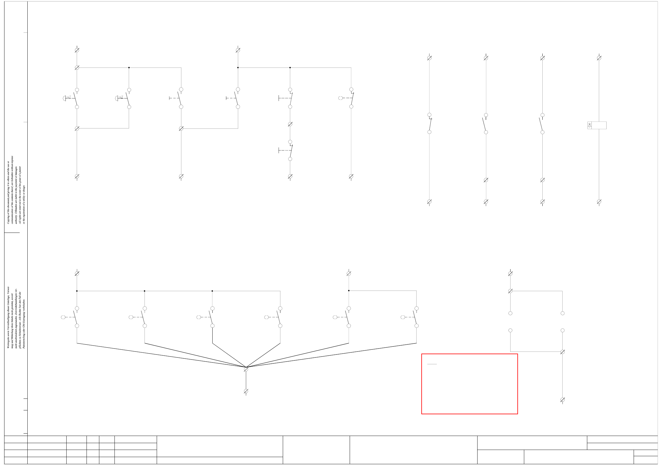
2 - 4
NH02-010101LD3 EMERGENCY-STOP circuit - signaling circuit with power supply 00375503-xx
Off button
00321432-xx vi
00321432-xx bk
Key-operated switch
00321434-xx bk
00321434-xx vi00321434-xx grpk
rdrd
00321434-xx rd
input conveyor
OFF
output conveyor
OFF
X1ka/6
X210/5
X1ka/5
00321528-xx S3
00321529-xx S3
X210/4
X1ka/4X1ka/2
X210/2
X210/1
00321529-xx S200321528-xx S200321529-xx S100321528-xx S1
On buttonEMERG. STOP
00321433-xx ye 00321436-xx ye 00321433-xx grpk
00321433-xx rd00321436-xx gn00321433-xx gn
ONON
output conveyorinput conveyoroutput conveyor
push-button
input conveyor
push-button
X210/3
00321416-xx S1
00321417-xx S1 00321614-xx S1
14
1313
1414
13
00305818-xx wh
00305818-xx br
Cover protective
switch
output conveyor
00305817-xx br
00305817-xx wh
13
14
00303617-xx S1
13
14
A2 (-)
A1 (+)
23
24
X211/21X211/22
6
5
22
21
X212/4X212/4X212/4
K1
00321113-xx grbn00321113-xx whgn00321113-xx whye00321113-xx whgn
00321113-xx brgn00321113-xx yebr00321113-xx whgr
Software release
Monitoring K2
Control OnControl On
Monitoring K3
Software release
X212 terminal strip (I/O distributor)
X211 terminal strip (I/O distributor)
X210 terminal strip (I/O distributor)
Note:
13
14
Cover protective
lefthand side
switch
Cover protective
00321573-xx br
switch
righthand side
00321573-xx wh 00321574-xx wh
00321574-xx br
Cover protective
input conveyor
switch
preceding
switch
Cover protective
00305815-xx br
00305815-xx wh 00305816-xx wh
00305816-xx br
Cover protective
switch
succeeding
NH02_SH02.DWG
Stromlaufplan/Circuit diagram
SMD Placement System SIPLACE S-27 HM
2
2
EMERENCY-STOP circuit - signaling circuit
with power supply unit 00375503-xx
00353088-xx
Signaling circuit Signaling circuit Signaling circuit Signaling circuit
blbk blbk
monitoring of control ON and software release signal
Signaling circuits
Cover switch signaling circuit
EMERG.-STOP signaling circuits, ON/OFF push-buttons, key-operated switches
blbk
Cover open
machine
(Option)
00321421-xx S1 00321421-xx S1
(Option)
machine
Push-button Push-button Push-button
blbk
X2ka/6
00321113-xx pkbn
X1ka/1X1kb/1 X4ka -
X3ka + (+24VDC) X3ka + (+24VDC) + 24VDC + 24VDC + 24VDC
X3kb+ (+24VDC) X3ka+ (+24VDC)
X3ka + (+24VDC)
00375503-xx K3
00375503-xx K3 00375503-xx K2 00375503-xx K1
4
3
4
3
4
3
4
3
2
11
2
blbk blbk
1
2
Key-operated
switch
00321529-xx S4
Push-button
EMERG.-STOP EMERG.-STOP
Sheet
Sh.
EMERGENCY-STOP signaling circuit, MTC
blbk
X1ka/2
00322111-xx pk
X210/2
5c 00322104-xx/X57a
6c 00322104-xx/X57a
5c 00322105-xx/X57b
6c 00322105-xx/X57b
00322111-xx gr
blbk
X210/1
EMERG. STOP
00322112-xx pk
00322112-xx gr
MTC interface,MTC interface,
lefthand side righthand side
DateModifiedStatus Orig./Repl.f/Replaced byName Stand.
Author
Check.
Date
Mat. no.:
CAD file:
1.
1.
1.
30.05.05
30.05.05
30.05.05 Hi
Hi
Hi 30.05.2005
Hi
L&A EA
SIEMENS
NH02-010101LD3
Doc. status
Product status
Function status
X1ka/3
X1ka/1-8 SLIO Port1-Port8 Inputs
X2ka/9-16 SLIO Port9-Port16 Outputs
X1kb/1-8 SLIO Port1-Port8 Inputs
X2kb/9-16 SLIO Port9-Port16 Outputs
See page 4-4
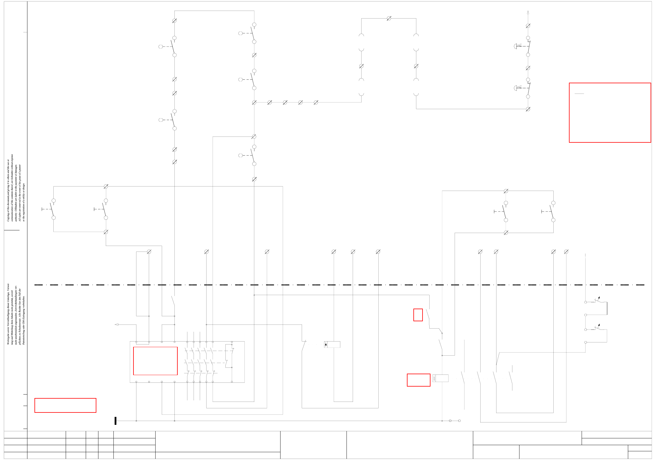
2 - 5
NH03-010101LD3 EMERGENCY-STOP circuit with power supply 00375539-xx (Japan version)
33 43 53
66
65
22
K3
21
13
14
K3
44
MP1 M
3RT1015
A2(-)
A1(+)
K2
A2
24614
A1
1
K2
14
13
5313
2
1
T2
43
K3
15
14
T1
bk
bk
24VAC
Fuse F10:2
Sheet 1 5/B
00375539-010101LD3
Sheet 1 5/B
00375539-010101LD3
Sheet 1 6/E
Sheet 1 6/E
bk
Temperature switch
00375539-xx
Power supply
X211/2
00321113-xx
wh
bn
X212:4
whgn
00321113-xx
X211:21
bngn
00321113-xx
00321113-xx
X2ka:6
gybn
X4ka -
00321113-xx
pkbn
X1kb:1
whgy
00321113-xx
X212:11
rd
00321113-xx
X212:4
whye
00321113-xx
X211:22
00321113-xx
yebn
X212:12
pk
00321113-xx
whpk
00321113-xx
X211/17
conveyor
00321432-xx gy
00321528-xx S2
3
00321432-xx pk
push-button
ON
input
4
conveyor
00321434-xx gy
00321113-xx gn
X211/16
00321529-xx S2
3
00321113-xx ye
output
00321434-xx pk
push-button
ON
4
00321113-xx gypk
00321432-xx gn
X211/18
X211/19
00321529-xx S2
00321113-xx rdbl
push-button
conveyor
output
ON
4
00321434-xx ye
00321432-xx ye
00321434-xx gn
3
4
00321528-xx S2
push-button
conveyor
ON
input
3
00321113-xx
bk
00321113-xx
vi
3
00321434-xx whye
Key-operated switch
00321529-xx S4
4
00321574-xx ye
00321574-xx gn
00321573-xx ye
00321573-xx gn
Connecting terminals for feeder crash sensors
jumpers X211/ 25-26, 26-27, 27-28 and 28-29.
WARNING: If you install the option remove
00321416-xx S1
lefthand side
OPTION: X211/ 25,26,27,28,29
00321434-xx bngn
X211/8
21
X211/29
28 2627 25
Protective cover
righthand side
Protective cover
00321417-xx S1
X211/9
22
switch
22
21
switch
00322070-xx bl
X211/15
00321113-xx bl
X211/14
X211/13
00305818-xx ye
00305818-xx gn
00305815-xx ye
00305815-xx gn
X211/11
Protective cover
Output conveyor
00303617-xx S1
22
switch
21
X211/12
Protective cover
Input conveyor
00303614-xx S1
22
21
X211/10
switch
OPTION: Cover switch, succeeding machine (00321421-xx)
Connect cable 00305817-xx to X211/13 gn - X211/14 ye
remove jumper X211/13 - X211/14.
WARNING: If you install the option
Connect cable 00305816-xx to X211/11 gn - X211/12 ye
OPTION: Cover switch, preceding machine (00321421-xx)
remove jumper X211/11 - X211/12.
WARNING: If you install the option
00322069-xx bn
00322111-xx ye
Component table,
lefthand side
00322069-xx bl
00322111-xx gn
lefthand side
MTC interface,
X211/5
1a 00322063-xx/X3ta
2c 00322063-xx/X3ta
3c 00322104-xx/X57a
4c 00322104-xx/X57a
X211/6
1a 00322064-xx/X37b
righthand side
Component table,
2c 00322064-xx/X37b
00322070-xx bn
00322112-xx ye
00322112-xx gn
MTC interface,
righthand side
X211/7
4c 00322105-xx/X57b
3c 00322105-xx/X57b
X211 terminal strip (I/O distributor)
X212 terminal strip (I/O distributor)
X1kb terminal strip (I/O distributor)
X2ka terminal strip (I/O distributor)
X4ka terminal strip (I/O distributor)
00321436-xx bn
EMERG.-STOP
00321529-xx S1
push-button
push-button
Output conveyor
00321528-xx S1
EMERG.-STOP
Input conveyor
1
2
X211/4
NH03_SH01.DWG
Stromlaufplan/Circuit diagram
SMD Placement System SIPLACE S-27 HM
1
2
EMERGENY-STOP circuit
with power supply
00353088-xx
Note:
00321433-xx bn
00321113-xx wh & bn
00321436-xx wh
00321433-xx wh
X211/3
2
1
X211/2
24V AC
K1:X1
Sh.
Sheet
DateStatus Name Stand. Orig./Repl.f/Replaced by
Author
Check.
Date
Mat. no.:
CAD file:
Modified
1.
1.
1.
30.05.05
30.05.05
30.05.05 Hi
Hi
Hi 30.05.2005
Hi
L&A EA
SIEMENS
NH03-010101LD3
Doc. status
Product status
Function status
00375539-xx (version for Japan)
GND
3TK2805
L2 X2 X4 X6 2414 4434 54
K1
L1 X1 X3 X5 13 23
See page 4-19
See page 4-19
See page 4-19
See page 4-4
See page 3-22