S27HM Circuit Diagrams.pdf - 第96页
3 - 7 0035308 8-010 601LD3 T ermin al block, I /O distri butor ( sh. 2 of 3) 8 1 2 34567 8 A B C D E F 1 X1kb 6 X2ka - X4ka 1 X1ka X211 22 2 8 14 22 15 16 29 Step motors Illumination A B C D E F 1 2 34567 Sign. circuit, …
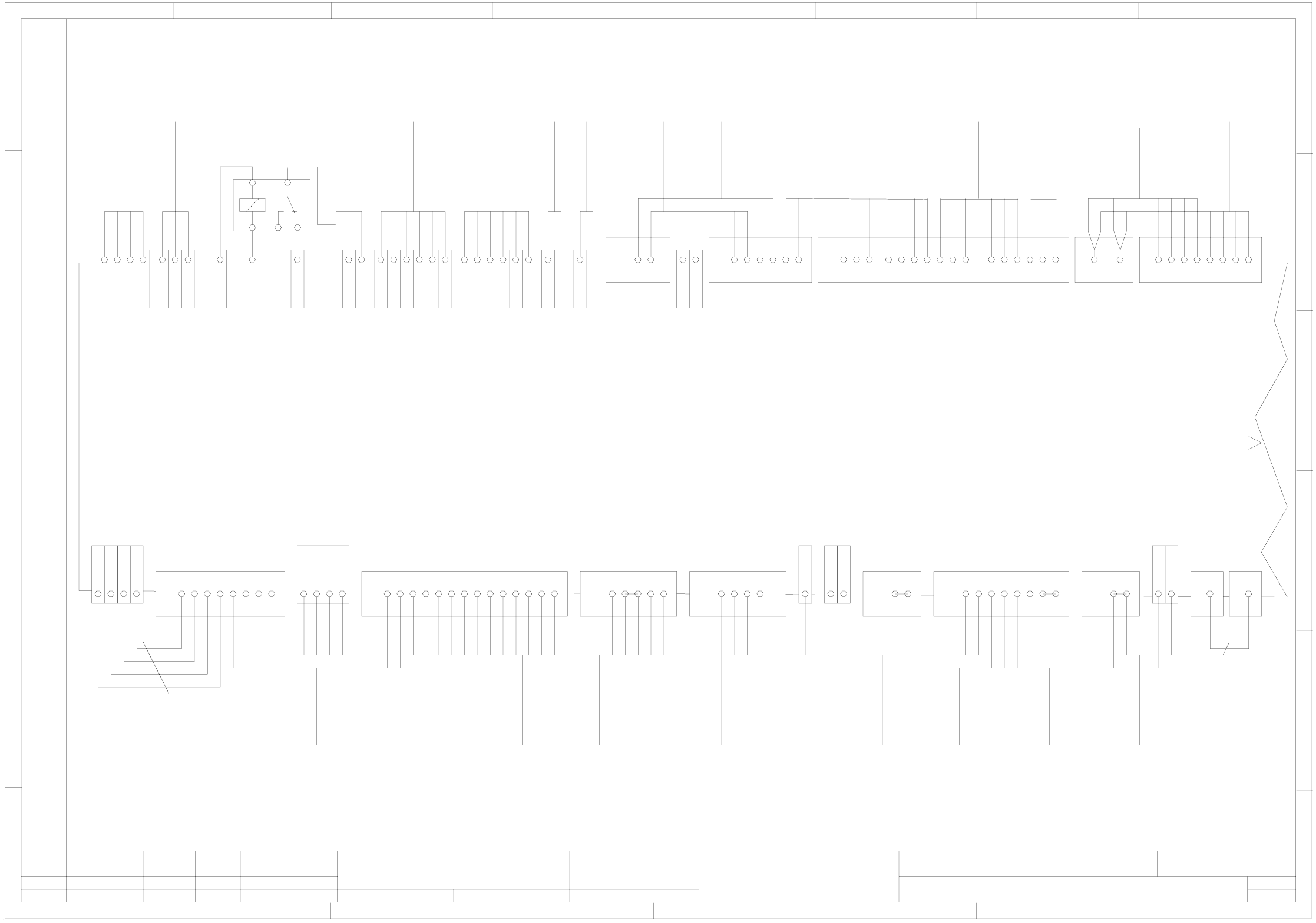
3 - 6
00353088-010601LD3 Terminal block, I/O distributor (sh. 1 of 3)
00303617-xx
Hood switch
downstream machine
00321421-xx
Option
To terminal block
Voltages
Attention !
Remove jumper X211:13-14, if a hood switch is installed!
To servo unit
Signaling circuit, protect. sw.5
+24V
+24V
Control circuit, protect. sw.5
Control circuit, protect. sw.5
Control circuit, protect. sw.6
Control circuit, protect. sw.6
Signaling circuit K1
Signaling circuit K2
+12V
+10V
+24V
+24V
+30V permanent
+30V switchable
GND
GND
+5V
Signaling circuit, emerg.-stop button
Signaling circuit, emerg.-stop button
GND, external emerg.-stop
External emerg.-stop
W PC (E-S-L)
W PC (E-S-L)
GND, external emerg.-stop
W PC (E-S-L)
External emerg.-stop
W PC (E-S-L)
GND
GND
1.5 mm²
To WPC interface
left-hand side
00322104-xx
right-hand side
00322105-xx
Emerg.-stop button
On button
Protect. cover opened
+24V
Signaling circuit, emerg.-stop button
+24V
Signaling circuit, On button
Signaling circuit, Off button
GND
+24V
Key-operated switch
Control circuit, emerg.-stop button
Control circuit, emerg.-stop button
To key-operated switch
From key-operated switch
Control circuit 2, On button
Control circuit 2, On button
Control circuit 1, On button
Control circuit 1, On button
W PC (E-S-L)
CO table (E-S-L)
CO table (E-S-L)
Feeder crash, left CO table
Control circuit, emerg.-stop button
Control circuit, emerg.-stop button
Signaling circuit, emerg.-stop button
Signaling circuit, emerg.-stop button
Signaling circuit, On button
Signaling circuit, On button
Control circuit, On button
Control circuit 2, On button
Control circuit 2, On button
Control circuit 1, On button
Control circuit 1, On button
Off button
+24V
+24V
Signaling circuit, protect. sw. 1
Signaling circuit, protect. sw. 2
Control circuit, protect. sw. 1
Control circuit, protect. sw. 1
Control circuit, protect. sw. 2
Control circuit, protect. sw. 2
Control circuit, protect. sw. 3
Control circuit, protect. sw. 3
Control circuit, protect. sw. 4
Control circuit, protect. sw. 4
Signaling circuit, protect. sw. 3
Signaling circuit, protect. sw. 4
+24V
+24V
wh
gn
ye
00321436-xx
To operator panel
Output conv.
00321529-xx
bn
bu&bk 0.5mm²
00321434-xx
gy&pk
vio
rd&bu
wh&ye
rd
bk
bn&gn
gy
pk
gn
ye
To operator panel
Output conv.
00321529-xx
00322069-xx
00322070-xx
bn
bu
bu
bn
CO tables
Interfaces
left
00322069-xx
right
00322070-xx
wh
bn
ye
gn
00321433-xx
To operator panel
Input conv.
00321528-xx
00321432-xx
To operator panel
Input conv.
00321528-xx
rd
gy&pk
bk
gy
pk
gn
ye
vio
bn
wh
gn
ye
00321573-xx
Hood switch
left
00321416-xx
bn
wh
gn
ye
00321574-xx
Hood switch
right
00321417-xx
00305815-xx
Hood switch
Input conv.
00303614-xx
gn
ye
gn
ye
00305816-xx
Hood switch
Upstream machine
00321421-xx
wh
wh
bn
bn
Attention !
Remove jumper X211:11-12, if a hood switch is installed!
Option
Continued on
Sheet 2
10 3 6
bn
gn
wh
00301485-xx
To video multiplexer
00322333-xx
GND
+5V
-15V
12
+50V
bu
4912
wh
GND
3
bk
bk
bk
A1
A2
12
11
bn
K 1
X3 kb +
GND
X4 ka -
X2 kb 3
+24V
Compressed air valve
Gantry distance
besondere für den Fall der Patenterteilung oder GM-Eintragung
pflichten zu Schadenersatz. Alle Rechte vorbehalten, ins
nicht ausdrücklich zugestanden. Zuwiderhandlungen ver-
wertung und Mitteilung ihres Inhalts nicht gestattet, soweit
Weitergabe sowie Vervielfältigung dieser Unterlage,Ver-
Confiado como secrete industrial. Nos reservamos todos los derechos.
Comunicado como segredo empresarial. Reservados todos os direilos.
Confie a titre de secret d´entreprise. Tous droits reserves.
Proprietary data, company confidential. All rights reserved.
L&A
SIEMENS
Date
Author
Check.
Stand.Status
1 .
1 .
6 .
NameDateModified
Function status
Product status
Document status
25.05.2000
25.05.2000
02.04.2003
Tuth
Tuth
Tuth
Orig.
L&A EA1 R&D
02.04.2003
Tuth
Repl. byRepl. f.
00353088-010601LD3
Terminal block, I/O distributor
SIPLACE S-27 HM
3
Sheet
Sh.
1
13 14 21 2213
X212
7 41293310
00305818-xx
00305817-xx
00306880-xx
00300182-xx
wh
wh
bn
bn
ye
ye
ye
gn
gn
gy
gn
bn
pk
bk
rd
bu
gy+pk
wh+bn
gn+ye
X210
12
gy
wh
X211
1 4512020 6 7
bn
gn
ye
pk
pk
gy
wh
bn
gn
ye
X211
1
X212
3
wh
00322112-xx
00322111-xx
Fault indicator lamp
Fault indicator lamp
Fault indicator lamp
GND
2 X1 ka
4 X1 ka
3 X1 ka
+ X3 ka
6 X1 ka
+ X3 ka
4 X2 kb
X210
14221345
X211
3 8 15 16 17418195725236
X210
21451
16 18 1917
+ X3 kb
5 X1 ka
X210
33
X211
29 9 10 109 111112
X210
33
+ X3 kb
+ X3 kb
+ X3 kb
ICOS-MC1
+24V
M54
GND
Pressure sensor
GND
GND
Nozzle ch. 1, closed
Nozzle ch. 1, open
Valve, nozzle ch. 1
GND
+24V
GND
Nozzle ch. 2, open
Valve, nozzle ch. 2
GND
Nozzle ch. 2, closed
To control board
Nozzle changer
Nozzle ch. 1 Nozzle ch. 2
Anti-crash, gantry 1
Signaling circuit, protect. sw.6
To conversion board
Gantry 1Gantry 2
Hood switch
Output conv.
8
1234567 8
A
B
C
D
E
F
X2 ka 1
X2 ka 2
X2 ka 3
X4 ka -
wh
gn
ye
bn
00321509-xx
To main fault indicator
X2 ka 4
X2 ka 5
- X4 kb
wh&gn
Component counter
A
B
C
D
E
F
1234567
X4 ka -
wh
gn
bn
00301486-xx
X1 ka 7
X4 ka -
wh
gn
00348262-xx
To video multiplexer
00322333-xx
To pneumatic system.
X4 kb -
X3 kb +
X1 kb 6
X1 kb 7
wh
pk
ye
bu
00317579-xxW 1
X2 kb 2
X4 kb -
rd
bn
X4 kb -
X3 kb +
X1 kb 4
X1 kb 5
wh
pk
ye
bu
00317579-xxW 2
X2 kb 1
X4 kb -
rd
bn
X1 kb 2
wh
bn
00344224-xx
X1 kb 3
wh
bn
00344225-xx
X210
33
X3 ka +
X3 ka +
X211
12
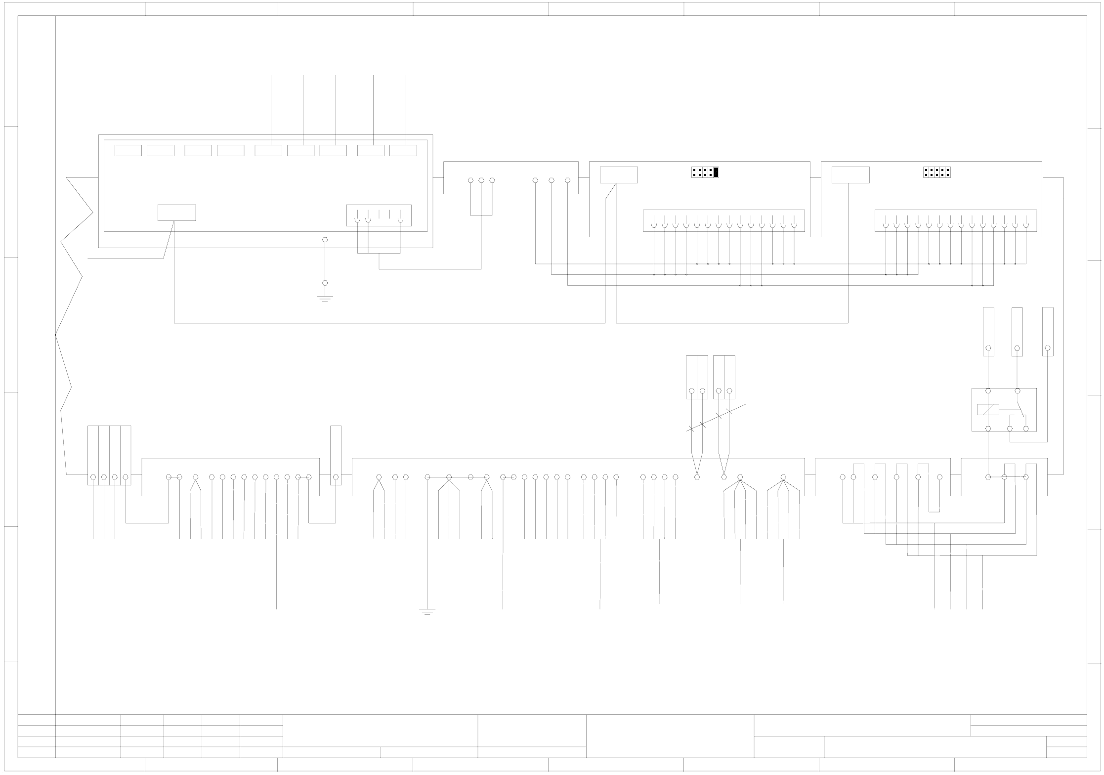
3 - 7
00353088-010601LD3 Terminal block, I/O distributor (sh. 2 of 3)
8
1234567 8
A
B
C
D
E
F
1 X1kb
6 X2ka
- X4ka
1 X1ka
X211
22
2
8
1422 15 16
29
Step motorsIllumination
A
B
C
D
E
F
1234567
Sign. circuit, software release (K3 monit.)
Software release K3
K3 contactor, GND
Sign. circuit K2, Control On
Control On, signaling circuit K1
24V AC for ext. emerg.-stop
To On button, from K1
From emerg.-stop circuit to K2
+24V
To feeder anti-crash sensor, left CO table, S1
00321113-xx
To power supply
gy&pk
vio
rd&bu
bk
gy
ye
Ground
(Frame)
00344213-xx
To control unit
00355468-xx
Remove the 4 jumpers inserted in X211:25-26; 26-27; 27-28; 28-29, when anti-crash sensors are installed for the feeders.
bn
Option
17 18 19 20 21 21
wh&gy
gy&bn
pk&bn
bu&bk
ye&bn
bn
wh
bu
gn
bn&gn
0.5 mm²
8 X1ka
0.5 mm²
bu&bk
X212
3 4564
rd&bu
gn
pk
gy&pk
34
wh&ye
wh&gn
bk
4 mm²
3 3 7810
bu&rd
bk
vio
besondere für den Fall der Patenterteilung oder GM-Eintragung
pflichten zu Schadenersatz. Alle Rechte vorbehalten, ins
nicht ausdrücklich zugestanden. Zuwiderhandlungen ver-
wertung und Mitteilung ihres Inhalts nicht gestattet, soweit
Weitergabe sowie Vervielfältigung dieser Unterlage,Ver-
Confiado como secrete industrial. Nos reservamos todos los derechos.
Comunicado como segredo empresarial. Reservados todos os direilos.
Confie a titre de secret d´entreprise. Tous droits reserves.
Proprietary data, company confidential. All rights reserved.
L&A
SIEMENS
Date
Author
Check.
Stand.Status
1 .
1 .
6 .
NameDateModified
Function status
Product status
Document status
25.05.2000
25.05.2000
02.04.2003
Tuth
Tuth
Tuth
Orig.
L&A EA1 R&D
02.04.2003
Tuth
Repl. byRepl. f.
00353088-010601LD3
Terminal block, I/O distributor
SIPLACE S-27 HM
3
Sheet
Sh.
2
+24V
00363412-xx
wh&gn
bn
ye&pk&rd
00344226-xx
gn
ye
4
10
113
00363413-xx
bn
ye&pk&rd
4
00344227-xx
4
gn
ye
gy
pk
pk
+24V
+24V
GND
GND
+5V
+5V
+24V
34
GND
+24V
50VDC release via K2
11 12
rd
pk
+50V DC
gy&bu
wh&gn
gy&bu
+50VDC via K2
+50VDC via K2
+24V
wh
gn
bn
+24V
GND
+5V
00360126-01
123 45
X21kc
+24V
+30V
X22kc
Conveyor control
TSP 201 (kc)
X1kc X2kc X4kc X5kc X23kc X24kcX11kc X12kc X13kc
GND
00xxxxxx-xx
wh
bn
gn
PE terminal
(00358068-xx)
(00360305-xx)
ye&gn
1.5 mm²
00363416-xx
To conversion board
Conveyor
00363417-xx
00363418-xx
00xxxxxx-xx
bn
bu&bk
Signal interface
Upstreammach.
Track 2 (left)
Signal interface
Downstream mach.
Track 1 (left)
Signal interface
Upstream mach.
Track 1 (left)
A1
A2
12
11
K2
X4 kb -
X212
13 1413
gn
X1 kb 8
X3 kb +
14
wh
wh
wh
gn
gn
gn
bk
bk
bn
bubk
Feeder anti-crash sensors
Attention !
00355468-xx
00355468-xx
00355468-xx
gy
wh
bn
ye
26 2725 28
X211
8
wh
Control On, sign. circuit K2
Control On, sign. circuit K2
To software relay K3
From software relay K3
From On button, to K1
To On button, from K2
From On button, to K2
External emerg.-stop circuit (WPC)
Control On, signaling circuit K1
Control On K1
GND
GND
GND
GND
+24V
+24V
+15V
-15V
+12V
-12V
+5V
bn
bn
bn
From feeder anti-crash sensor, left CO table, S1
To feeder anti-crash sensor, left CO table, S2
From feeder anti-crash sensor, left CO table, S2
To feeder anti-crash sensor, right CO table, S1
From feeder anti-crash sensor, right CO table, S1
To feeder anti-crash sensor, right CO table, S2
From feeder anti-crash sensor, right CO table, S2
From CO table (E-S-L)
left
S1
left
S2
right
S1
right
S2
To conversion board
Gantry 1
To conversion board
Gantry 2
To conversion board
Gantry 1
To conversion board
Gantry 2
123 4567 89
10 11 12 13 14
X18ka
X17ka
X19ka
SLIO (ka)
X212
423
+24V
+5V
Signal interface
Downstream mach.
Track 2 (left)
410
+24V
GND
+5V
GND
123 4567 89
10 11 12 13 14
X18kb
X17kb
X19kb
SLIO (kb)
+24V
GND
+5V
GND
3
+30V switchable
GND
- X4ka
- X4kb
+ X3ka
+ X3kb
Ribbon cable, 14-pin
Combine wires 1,2,3,4 into one wire end ferrule
Combine wires 5,6,7,8,12,13,14 into one wire end ferrule
Combine wires 9,10,11 into one wire end ferrule
00363926-xx CAN bus ribbon cable, 10-pin
00360124-01
To barcode scanner
Signal / voltage
0.50 mm²
Power supply system
SLIO_module
4
10
113
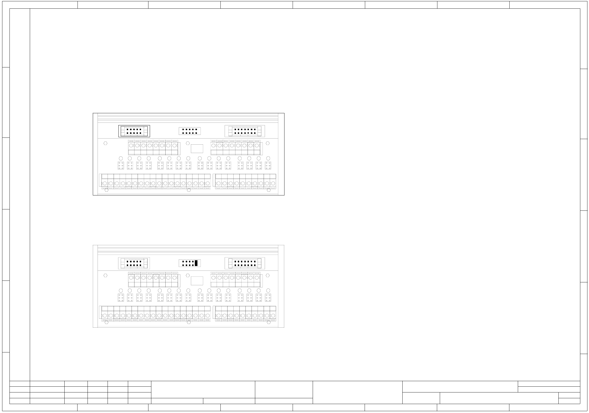
3 - 8
00353088-010601LD3 Terminal block, I/O distributor (sh. 3 of 3)
1
X18 X19 X17
X5
X1
X2
X3
X4
H2 H3 H4H1
X6 X7 X8 X9 X10 X11 X12 X13 X14 X15 X16 X17 X18 X19 X20
H6 H7 H8H5 H10 H11 H12H9
H14 H15 H16H13
12345678 12345678
P
++++++++
PM
----------------
M
ka
SLIO module I/O assignment with terminal adapter:
Due to the plug-in adapter on the SLIO module, it is compulsory to program:
the first byte for inputs (port 1-8) and the second byte for outputs (port 9-16)
(SLIO port 1 to port 8 Plug-in adapter X1-1 to X1-8)
(SLIO Port 9 to port 16 Plug-in adapter X2-1 to X2-8)
I/O module (ka)
Coding: Address 0 no jumper inserted
Inputs
Port 1 X1-1 Control on (K2) ( 1-> K2 on )
Port 2 X1-2 Emerg.-stop button ( 1-> actuated )
Port 3 X1-3 Protective cover ( 1-> opened )
Port 4 X1-4 "On" button ( 1-> actuated )
Port 5 X1-5 "Off" button ( 0-> actuated )
Port 6 X1-6 Key switch ( 0-> actuated )
Port 7 X1-7 Pressure sensor ( 1-> air present)
Port 8 X1-8 Control on (K1) ( 1-> K1 on )
Outputs
Port 9 X2-1 Main fault indicator, on the right, white
Port 10 X2-2 Main fault indicator ready, green
Port 11 X2-3 Main fault indicator, on the left, white
Port 12 X2-4 ICOS MC1
Port 13 X2-5 MC1 (M54)
Port 14 X2-6 Software release Control On
Port 15 X2-7 Fill level
Port 16 X2-8 n.u.
I/O module (kb)
Coding: address 1 jumper on X19kb pin 1-2
Inputs
Port 1 X1-1 Protect. cover monitoring (software release)
Port 2 X1-2 Anti-crash, gantry 1
Port 3 X1-3 Distance sensor
Port 4 X1-4 Sensor Nozzle changer, gantry 2 closed
Port 5 X1-5 Sensor Nozzle changer, gantry 2 open
Port 6 X1-6 Sensor Nozzle changer, gantry 1 closed
Port 7 X1-7 Sensor Nozzle changer, gantry 1 open
Port 8 X1-8 Feeder anti-crash sensor
Outputs
Port 9 X2-1 Valve Nozzle changer, gantry 2
Port 10 X2-2 Valve Nozzle changer, gantry 1
Port 11 X2-3 Valve Compressed air on
Port 12 X2-4 Component counter
Port 13 X2-5 n.u.
Port 14 X2-6 n.u.
Port 15 X2-7 n.u.
Port 16 X2-8 n.u.
1 10
1
2
9
1
X18 X19 X17
X5
X1
X2
X3
X4
H2 H3 H4H1
X6 X7 X8 X9 X10 X11 X12 X13 X14 X15 X16 X17 X18 X19 X20
H6 H7 H8H5 H10 H11 H12H9
H14 H15 H16H13
12345678 12345678
P
++++++++
P
M
----------------
M
67 8
1234567 8
A
B
C
D
E
F
kb
A
B
C
D
E
F
12 3 4 5
1 10
1
2
9
besondere für den Fall der Patenterteilung oder GM-Eintragung
pflichten zu Schadenersatz. Alle Rechte vorbehalten, ins
nicht ausdrücklich zugestanden. Zuwiderhandlungen ver-
wertung und Mitteilung ihres Inhalts nicht gestattet, soweit
Weitergabe sowie Vervielfältigung dieser Unterlage,Ver-
Confiado como secrete industrial. Nos reservamos todos los derechos.
Comunicado como segredo empresarial. Reservados todos os direilos.
Confie a titre de secret d´entreprise. Tous droits reserves.
Proprietary data, company confidential. All rights reserved.
L&A
SIEMENS
Date
Author
Check.
Stand.Status
1 .
1 .
6 .
NameDateModified
Function status
Product status
Document status
25.05.2000
25.05.2000
02.04.2003
Tuth
Tuth
Tuth
Orig.
L&A EA1 R&D
02.04.2003
Tuth
Repl. byRepl. f.
00353088-010601LD3
Terminal block, I/O distributor
SIPLACE S-27 HM
3
Sheet
Sh.
3