S27HM Circuit Diagrams.pdf - 第98页
3 - 9 0035447 6-010 301LD3 Servo u nit, S- 27 HM, basic mo dule, w iring ( sh. 1 o f 5) 5 SIEMENS A G PLEA1 E Status Modifie d Da te Name Standard Orig. Repl.f. Repl. by Document status Product status Function status Dat…
3 - 8
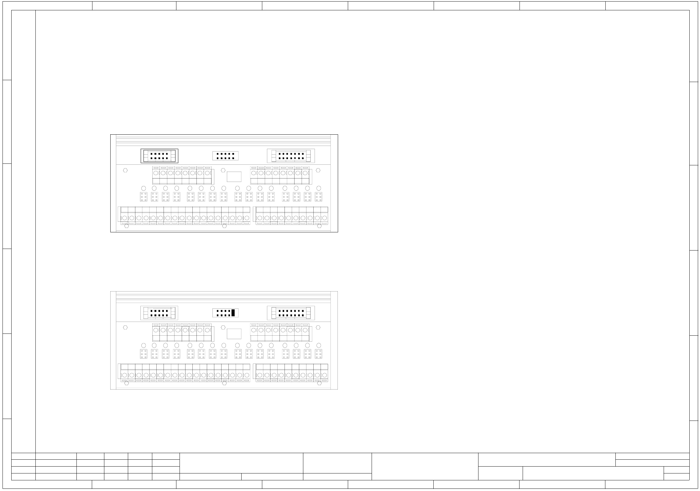
00353088-010601LD3 Terminal block, I/O distributor (sh. 3 of 3)
1
X18 X19 X17
X5
X1
X2
X3
X4
H2 H3 H4H1
X6 X7 X8 X9 X10 X11 X12 X13 X14 X15 X16 X17 X18 X19 X20
H6 H7 H8H5 H10 H11 H12H9
H14 H15 H16H13
12345678 12345678
P
++++++++
PM
----------------
M
ka
SLIO module I/O assignment with terminal adapter:
Due to the plug-in adapter on the SLIO module, it is compulsory to program:
the first byte for inputs (port 1-8) and the second byte for outputs (port 9-16)
(SLIO port 1 to port 8 Plug-in adapter X1-1 to X1-8)
(SLIO Port 9 to port 16 Plug-in adapter X2-1 to X2-8)
I/O module (ka)
Coding: Address 0 no jumper inserted
Inputs
Port 1 X1-1 Control on (K2) ( 1-> K2 on )
Port 2 X1-2 Emerg.-stop button ( 1-> actuated )
Port 3 X1-3 Protective cover ( 1-> opened )
Port 4 X1-4 "On" button ( 1-> actuated )
Port 5 X1-5 "Off" button ( 0-> actuated )
Port 6 X1-6 Key switch ( 0-> actuated )
Port 7 X1-7 Pressure sensor ( 1-> air present)
Port 8 X1-8 Control on (K1) ( 1-> K1 on )
Outputs
Port 9 X2-1 Main fault indicator, on the right, white
Port 10 X2-2 Main fault indicator ready, green
Port 11 X2-3 Main fault indicator, on the left, white
Port 12 X2-4 ICOS MC1
Port 13 X2-5 MC1 (M54)
Port 14 X2-6 Software release Control On
Port 15 X2-7 Fill level
Port 16 X2-8 n.u.
I/O module (kb)
Coding: address 1 jumper on X19kb pin 1-2
Inputs
Port 1 X1-1 Protect. cover monitoring (software release)
Port 2 X1-2 Anti-crash, gantry 1
Port 3 X1-3 Distance sensor
Port 4 X1-4 Sensor Nozzle changer, gantry 2 closed
Port 5 X1-5 Sensor Nozzle changer, gantry 2 open
Port 6 X1-6 Sensor Nozzle changer, gantry 1 closed
Port 7 X1-7 Sensor Nozzle changer, gantry 1 open
Port 8 X1-8 Feeder anti-crash sensor
Outputs
Port 9 X2-1 Valve Nozzle changer, gantry 2
Port 10 X2-2 Valve Nozzle changer, gantry 1
Port 11 X2-3 Valve Compressed air on
Port 12 X2-4 Component counter
Port 13 X2-5 n.u.
Port 14 X2-6 n.u.
Port 15 X2-7 n.u.
Port 16 X2-8 n.u.
1 10
1
2
9
1
X18 X19 X17
X5
X1
X2
X3
X4
H2 H3 H4H1
X6 X7 X8 X9 X10 X11 X12 X13 X14 X15 X16 X17 X18 X19 X20
H6 H7 H8H5 H10 H11 H12H9
H14 H15 H16H13
12345678 12345678
P
++++++++
P
M
----------------
M
67 8
1234567 8
A
B
C
D
E
F
kb
A
B
C
D
E
F
12 3 4 5
1 10
1
2
9
besondere für den Fall der Patenterteilung oder GM-Eintragung
pflichten zu Schadenersatz. Alle Rechte vorbehalten, ins
nicht ausdrücklich zugestanden. Zuwiderhandlungen ver-
wertung und Mitteilung ihres Inhalts nicht gestattet, soweit
Weitergabe sowie Vervielfältigung dieser Unterlage,Ver-
Confiado como secrete industrial. Nos reservamos todos los derechos.
Comunicado como segredo empresarial. Reservados todos os direilos.
Confie a titre de secret d´entreprise. Tous droits reserves.
Proprietary data, company confidential. All rights reserved.
L&A
SIEMENS
Date
Author
Check.
Stand.Status
1 .
1 .
6 .
NameDateModified
Function status
Product status
Document status
25.05.2000
25.05.2000
02.04.2003
Tuth
Tuth
Tuth
Orig.
L&A EA1 R&D
02.04.2003
Tuth
Repl. byRepl. f.
00353088-010601LD3
Terminal block, I/O distributor
SIPLACE S-27 HM
3
Sheet
Sh.
3
3 - 9
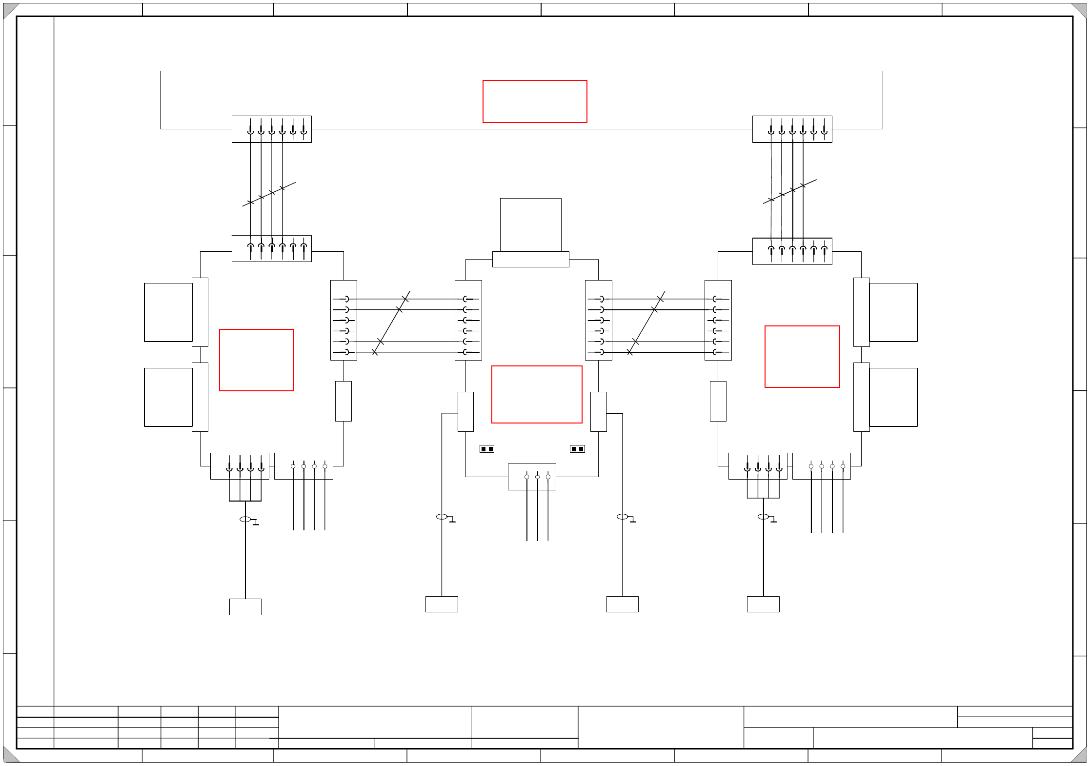
00354476-010301LD3 Servo unit, S-27 HM, basic module, wiring (sh. 1 of 5)
5
SIEMENS AG
PLEA1 E
Status Modified Date Name Standard Orig. Repl.f. Repl. by
Document status
Product status
Function status Date
Author
Check.
Sheet
Sh.
W
e
i
t
e
r
g
a
b
e
s
o
w
i
e
V
e
r
v
i
e
l
f
ä
l
t
i
g
u
n
g
d
i
e
s
e
r
U
n
t
e
r
l
a
g
e
,
V
e
r
-
w
e
r
t
u
n
g
u
n
d
M
i
t
t
e
i
l
u
n
g
i
h
r
e
s
I
n
h
a
l
t
s
n
i
c
h
t
g
e
s
t
a
t
t
e
t
,
s
o
w
e
i
t
n
i
c
h
t
a
u
s
d
r
ü
c
k
l
i
c
h
z
u
g
e
s
t
a
n
d
e
n
.
Z
u
w
i
d
e
r
h
a
n
d
l
u
n
g
e
n
v
e
r
-
p
f
l
i
c
h
t
e
n
z
u
S
c
h
a
d
e
n
e
r
s
a
t
z
.
A
l
l
e
R
e
c
h
t
e
v
o
r
b
e
h
a
l
t
e
n
,
i
n
s
b
e
s
o
n
d
e
r
e
f
ü
r
d
e
n
F
a
l
l
d
e
r
P
a
t
e
n
t
e
r
t
e
i
l
u
n
g
o
d
e
r
G
M
-
E
i
n
t
r
a
g
u
n
g
P
r
o
p
r
i
e
t
a
r
y
d
a
t
e
,
c
o
m
p
a
n
y
c
o
n
f
i
d
e
n
t
i
a
l
.
A
l
l
r
i
g
h
t
s
r
e
s
e
r
v
d
.
C
o
n
f
i
e
a
t
i
t
r
e
d
e
s
e
c
r
e
t
d
´
e
n
t
r
e
p
r
i
s
e
.
T
o
u
s
d
r
o
i
t
s
r
e
s
e
r
v
e
s
.
C
o
m
u
n
i
c
a
d
o
c
o
m
o
s
e
g
r
e
d
o
e
m
p
r
e
s
a
r
i
a
l
.
R
e
s
e
r
v
a
d
o
s
t
o
d
o
s
o
s
d
i
r
e
i
l
o
s
.
C
o
n
f
i
a
d
o
c
o
m
o
s
e
c
r
e
t
e
i
n
d
u
s
t
r
i
a
l
.
N
o
s
r
e
s
e
r
v
a
m
o
s
t
o
d
o
s
l
o
s
d
e
r
e
c
h
o
s
.
SIPLACE S27 HM SMD Placement System
Servo unit, basic module, wiring
A
B
C
D
E
F
1 2 3 4 5 6 7 8
1
2 3 4 5 6 7 8
A
B
C
D
E
F
3.
1.
1.
25.05.2000
17.07.2001
25.05.2000
Tuth
Tuth
Tuth 17.07.2001
Tuth
00354476-010301LD3
X
1
v
a
S
e
r
v
o
X
-
a
x
i
s
1
Backplane
x-axis 1
A18
(va)
1234
X
7
v
a
X
6
v
a
1234
X
2
v
a
D
y
n
a
m
i
c
b
r
a
k
e
M
o
t
o
r
U
M
o
t
o
r
V
M
o
t
o
r
W
M
o
t
o
r
G
N
D
P
o
w
e
r
+
1
5
0
V
P
o
w
e
r
G
N
D
P
1
5
V
N
1
5
V
1
2
3
4
5
6
X4va
A-GND
Tachometer
A-GND
PTC
X
5
v
a
123456
A
-
G
N
D
T
a
c
h
o
m
e
t
e
r
A
n
t
i
-
c
r
a
s
h
P
1
5
V
X
3
v
a
k
e
y
key
1
2
3
4
5
6
X5ve
A-GND
PTC
123
X
6
v
e
G
N
D
P
1
5
V
N
1
5
V
1
2
3
4
5
6
X4ve
Tacho_Y_N
Tacho_Y_P
A-GND
PTC
X
2
v
e
Backplane
Tachometer analysis
A29
(ve)
X1ve
Tachometer
X / Y
X
1
v
b
S
e
r
v
o
Y
-
a
x
i
s
1
Backplane
Y-axis 1
A19
(vb)
X
5
v
b
123456
1234
X
7
v
b
X
6
v
b
1234
1
2
3
4
5
6
X4vb
X
2
v
b
D
y
n
a
m
i
c
b
r
a
k
e
X
3
v
b
M
o
t
o
r
U
M
o
t
o
r
V
M
o
t
o
r
W
M
o
t
o
r
G
N
D
P
o
w
e
r
+
1
5
0
V
P
o
w
e
r
G
N
D
P
1
5
V
N
1
5
V
A-GND
Tachometer
A-GND
PTC
A
-
G
N
D
T
a
c
h
o
m
e
t
e
r
A
n
t
i
-
c
r
a
s
h
P
1
5
V
k
e
y
key
X
1
1
b
123456
T
a
c
h
o
m
e
t
e
r
-
T
a
c
h
o
m
e
t
e
r
+
A
n
t
i
-
c
r
a
s
h
P
1
5
V
X
1
1
a
123456
T
a
c
h
o
m
e
t
e
r
-
T
a
c
h
o
m
e
t
e
r
+
A
n
t
i
-
c
r
a
s
h
P
1
5
V
S
t
a
r
p
o
i
n
t
0
0
9
0
0
3
5
4
4
7
1
-
x
x
X31a
y
e
/
g
n
b
r
b
l
b
k
S
t
a
r
p
o
i
n
t
0
0
7
P
o
w
e
r
s
u
p
p
l
y
u
n
i
t
+
1
5
V
v
i
o
P
o
w
e
r
s
u
p
p
l
y
u
n
i
t
-
1
5
V
w
h
p
k
b
k
p
k
g
y
0.25mm
2
ye/bk
0.25mm
2
wh
0.25mm
2
wh
S
t
a
r
p
o
i
n
t
0
0
7
P
o
w
e
r
s
u
p
p
l
y
u
n
i
t
+
1
5
V
P
o
w
e
r
s
u
p
p
l
y
u
n
i
t
-
1
5
V
w
h
p
k
b
k
p
k
g
y
S
t
a
r
p
o
i
n
t
0
0
9
S
t
a
r
p
o
i
n
t
0
0
7
P
o
w
e
r
s
u
p
p
l
y
u
n
i
t
+
1
5
V
v
i
o
P
o
w
e
r
s
u
p
p
l
y
u
n
i
t
-
1
5
V
w
h
p
k
b
k
p
k
g
y
0
0
3
5
4
4
7
3
-
x
x
X36aa
y
e
/
g
n
b
r
b
l
b
k
Anit-crash board
X
3
v
e
0
0
3
5
4
4
1
7
-
x
x
X32a
0
0
3
5
4
4
1
9
-
x
x
X38aa
0.25mm
2
ye/bk
key
key
Tacho_X_N
Tacho_X_P
k
e
y
k
e
y
1
J1 J2
Please note !
Insert jumpers J1 and J2 on the backplane for the tachometer analysis of gantry 2 ( A30 vs).
(This way, the sense of rotation and the tachometer voltage is adjusted.)
analysis
See page 5-5
See page 5-26
See page 5-26
See page 5-27
3 - 10
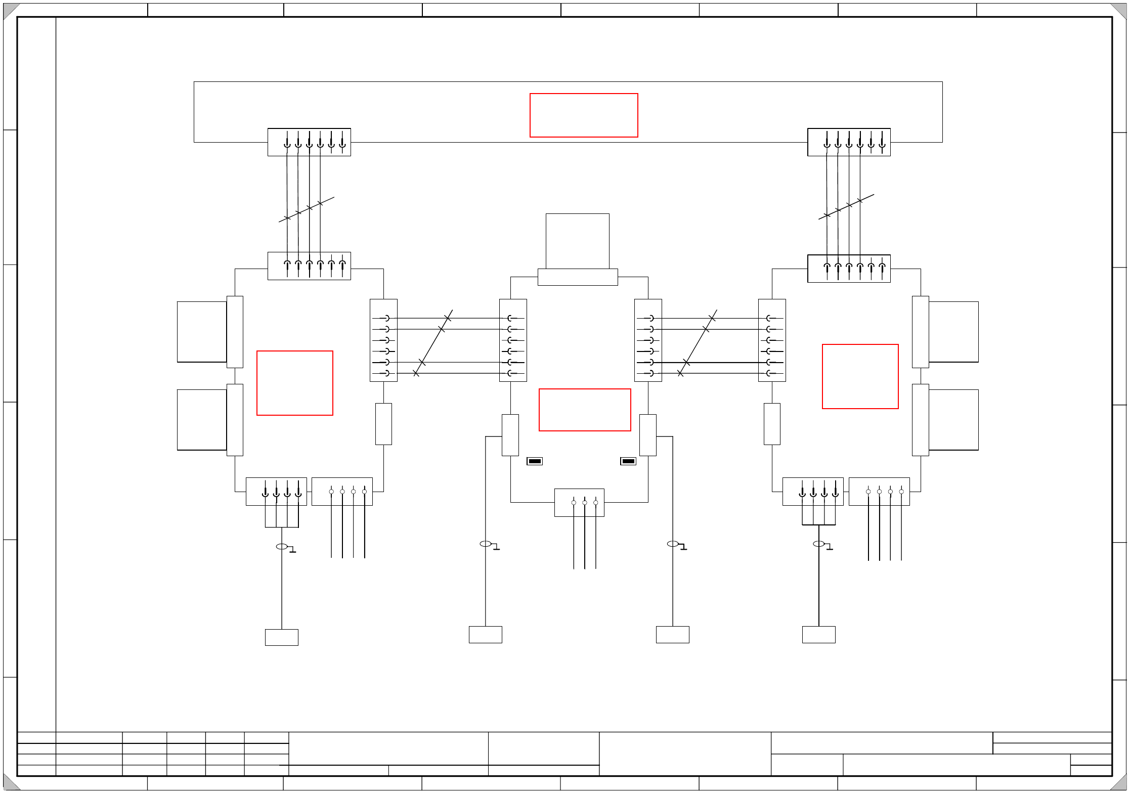
00354476-010301LD3 Servo unit, S-27 HM, basic module, wiring (sh. 2 of 5)
5
SIEMENS AG
PLEA1 E
Status Modified Date Name Standard Orig. Repl.f. Repl. by
Document status
Product status
Function status Date
Author
Check.
Sheet
Sh.
W
e
i
t
e
r
g
a
b
e
s
o
w
i
e
V
e
r
v
i
e
l
f
ä
l
t
i
g
u
n
g
d
i
e
s
e
r
U
n
t
e
r
l
a
g
e
,
V
e
r
-
w
e
r
t
u
n
g
u
n
d
M
i
t
t
e
i
l
u
n
g
i
h
r
e
s
I
n
h
a
l
t
s
n
i
c
h
t
g
e
s
t
a
t
t
e
t
,
s
o
w
e
i
t
n
i
c
h
t
a
u
s
d
r
ü
c
k
l
i
c
h
z
u
g
e
s
t
a
n
d
e
n
.
Z
u
w
i
d
e
r
h
a
n
d
l
u
n
g
e
n
v
e
r
-
p
f
l
i
c
h
t
e
n
z
u
S
c
h
a
d
e
n
e
r
s
a
t
z
.
A
l
l
e
R
e
c
h
t
e
v
o
r
b
e
h
a
l
t
e
n
,
i
n
s
b
e
s
o
n
d
e
r
e
f
ü
r
d
e
n
F
a
l
l
d
e
r
P
a
t
e
n
t
e
r
t
e
i
l
u
n
g
o
d
e
r
G
M
-
E
i
n
t
r
a
g
u
n
g
P
r
o
p
r
i
e
t
a
r
y
d
a
t
e
,
c
o
m
p
a
n
y
c
o
n
f
i
d
e
n
t
i
a
l
.
A
l
l
r
i
g
h
t
s
r
e
s
e
r
v
d
.
C
o
n
f
i
e
a
t
i
t
r
e
d
e
s
e
c
r
e
t
d
´
e
n
t
r
e
p
r
i
s
e
.
T
o
u
s
d
r
o
i
t
s
r
e
s
e
r
v
e
s
.
C
o
m
u
n
i
c
a
d
o
c
o
m
o
s
e
g
r
e
d
o
e
m
p
r
e
s
a
r
i
a
l
.
R
e
s
e
r
v
a
d
o
s
t
o
d
o
s
o
s
d
i
r
e
i
l
o
s
.
C
o
n
f
i
a
d
o
c
o
m
o
s
e
c
r
e
t
e
i
n
d
u
s
t
r
i
a
l
.
N
o
s
r
e
s
e
r
v
a
m
o
s
t
o
d
o
s
l
o
s
d
e
r
e
c
h
o
s
.
SIPLACE S27 HM SMD Placement System
Servo unit, basic module, wiring
A
B
C
D
E
F
1 2 3 4 5 6 7 8
1
2 3 4 5 6 7 8
A
B
C
D
E
F
3.
1.
1.
25.05.2000
17.07.2001
25.05.2000
Tuth
Tuth
Tuth 17.07.2001
Tuth
00354476-010301LD3
X
1
v
m
S
e
r
v
o
X
-
a
x
i
s
2
Backplane
X-axis 2
A23
(vm)
1234
X
7
v
m
X
6
v
m
1234
X
2
v
m
D
y
n
a
m
i
c
b
r
a
k
e
M
o
t
o
r
U
M
o
t
o
r
V
M
o
t
o
r
W
M
o
t
o
r
G
N
D
P
o
w
e
r
+
1
5
0
V
P
o
w
e
r
G
N
D
P
1
5
V
N
1
5
V
1
2
3
4
5
6
X4vm
A-GND
Tacho
A-GND
PTC
X
5
v
m
123456
A
-
G
N
D
T
a
c
h
o
m
e
t
e
r
A
n
t
i
-
c
r
a
s
h
P
1
5
V
X
3
v
m
k
e
y
key
1
2
3
4
5
6
X5vs
A-GND
PTC
123
X
6
v
s
G
N
D
P
1
5
V
N
1
5
V
1
2
3
4
5
6
X4vs
Tacho_X_N
Tacho_X_P
A-GND
PTC
X
2
v
s
Backplane
Tachometer analysis
A30
(vs)
X1vs
Tachometer
X / Y
X
1
v
n
S
e
r
v
o
Y
-
a
x
i
s
2
Backplane
Y-axis 2
A24
(vn)
X
5
v
n
123456
1234
X
7
v
m
X
6
v
m
1234
1
2
3
4
5
6
X4vn
X
2
v
n
D
y
n
a
m
i
c
b
r
a
k
e
X
3
v
n
M
o
t
o
r
U
M
o
t
o
r
V
M
o
t
o
r
W
M
o
t
o
r
G
N
D
P
o
w
e
r
+
1
5
0
V
P
o
w
e
r
G
N
D
P
1
5
V
N
1
5
V
A-GND
Tachometer
A-GND
PTC
A
-
G
N
D
T
a
c
h
o
C
r
a
s
h
P
1
5
V
k
e
y
key
X
1
1
d
123456
T
a
c
h
o
m
e
t
e
r
-
T
a
c
h
o
m
e
t
e
r
+
A
n
t
i
-
c
r
a
s
h
P
1
5
V
X
1
1
c
123456
T
a
c
h
o
m
e
t
e
r
-
T
a
c
h
o
m
e
t
e
r
+
A
n
t
i
-
c
r
a
s
h
P
1
5
V
S
t
a
r
p
o
i
n
t
0
0
9
0
0
3
5
4
4
7
2
-
x
x
X31b
y
e
/
g
n
b
r
b
l
b
k
S
t
a
r
p
o
i
n
t
0
0
7
P
o
w
e
r
s
u
p
p
l
y
u
n
i
t
+
1
5
V
v
i
o
P
o
w
e
r
s
u
p
p
l
y
u
n
i
t
-
1
5
V
w
h
p
k
b
k
p
k
g
y
0.25mm
2
ye/bk
0.25mm
2
wh
0.25mm
2
wh
S
t
a
r
p
o
i
n
t
0
0
7
P
o
w
e
r
s
u
p
p
l
y
u
n
i
t
+
1
5
V
P
o
w
e
r
s
u
p
p
l
y
u
n
i
t
-
1
5
V
w
h
p
k
b
k
p
k
g
y
S
t
a
r
p
o
i
n
t
0
0
9
S
t
a
r
p
o
i
n
t
0
0
7
P
o
w
e
r
s
u
p
p
l
y
u
n
i
t
+
1
5
V
v
i
o
P
o
w
e
r
s
u
p
p
l
y
u
n
i
t
-
1
5
V
w
h
p
k
b
k
p
k
g
y
0
0
3
5
4
4
7
4
-
x
x
X36ba
y
e
/
g
n
b
r
b
l
b
k
Anti-crash board
X
3
v
s
0
0
3
5
4
4
1
8
-
x
x
X32b
0
0
3
5
4
4
2
0
-
x
x
X38ba
0.25mm
2
ye/bk
key
key
Tacho_Y_N
Tacho_Y_P
2
Please note !
Insert jumpers J1 and J2 on the backplane for the tachometer analysis of gantry 2 ( A30 vs).
(This way, the sense of rotation and the tachometer voltage is adjusted.)
J1 J2
analysis
See page 5-5
See page 5-26
See page 5-26
See page 5-27