S27HM Circuit Diagrams.pdf - 第99页
3 - 10 0035447 6-010 301LD3 Servo u nit, S- 27 HM, basic mo dule, w iring ( sh. 2 o f 5) 5 SIEMENS A G PLEA1 E Status Modifie d Da te Name Standard Orig. Repl.f. Repl. by Document status Product status Function status Da…
3 - 9
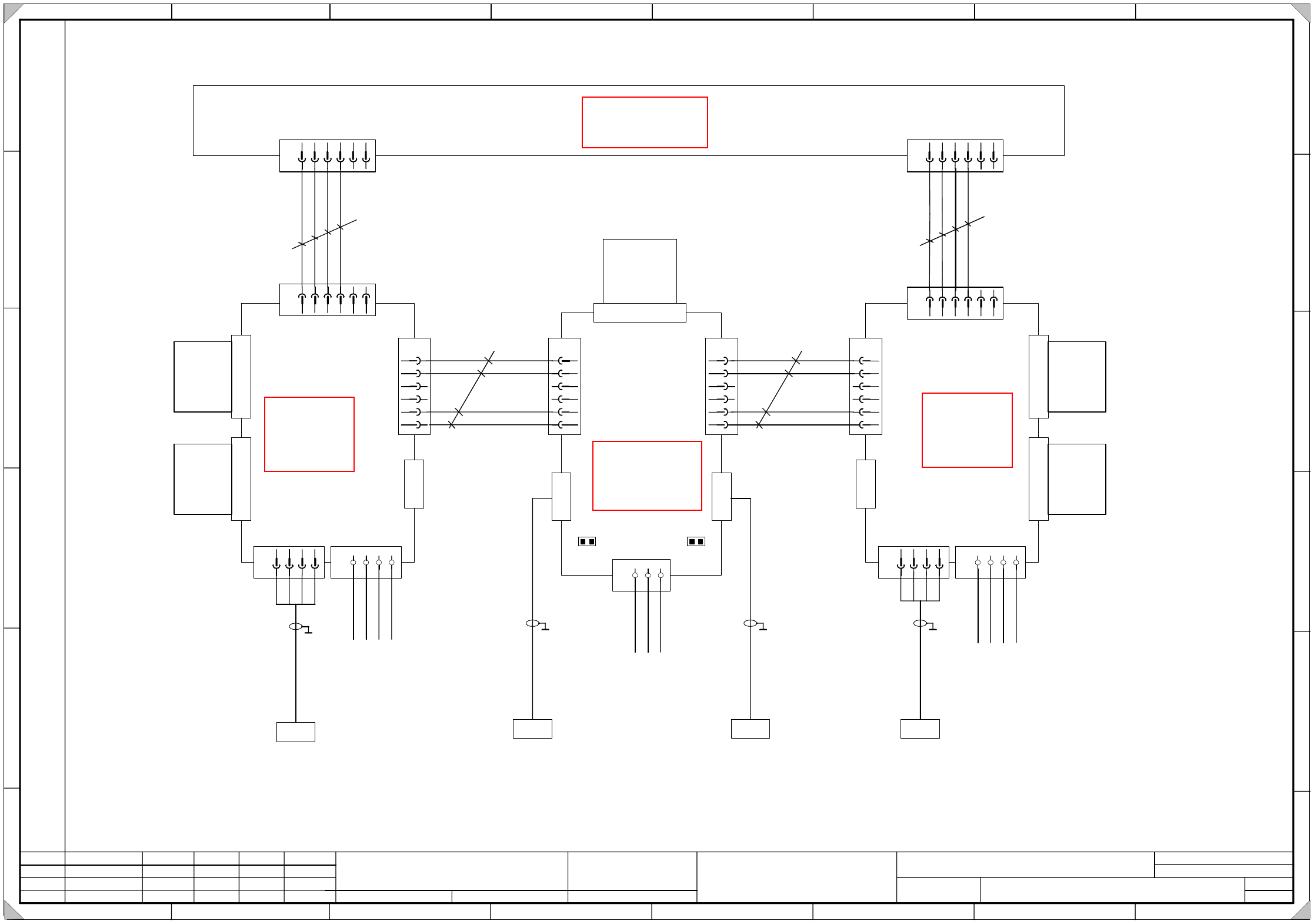
00354476-010301LD3 Servo unit, S-27 HM, basic module, wiring (sh. 1 of 5)
5
SIEMENS AG
PLEA1 E
Status Modified Date Name Standard Orig. Repl.f. Repl. by
Document status
Product status
Function status Date
Author
Check.
Sheet
Sh.
W
e
i
t
e
r
g
a
b
e
s
o
w
i
e
V
e
r
v
i
e
l
f
ä
l
t
i
g
u
n
g
d
i
e
s
e
r
U
n
t
e
r
l
a
g
e
,
V
e
r
-
w
e
r
t
u
n
g
u
n
d
M
i
t
t
e
i
l
u
n
g
i
h
r
e
s
I
n
h
a
l
t
s
n
i
c
h
t
g
e
s
t
a
t
t
e
t
,
s
o
w
e
i
t
n
i
c
h
t
a
u
s
d
r
ü
c
k
l
i
c
h
z
u
g
e
s
t
a
n
d
e
n
.
Z
u
w
i
d
e
r
h
a
n
d
l
u
n
g
e
n
v
e
r
-
p
f
l
i
c
h
t
e
n
z
u
S
c
h
a
d
e
n
e
r
s
a
t
z
.
A
l
l
e
R
e
c
h
t
e
v
o
r
b
e
h
a
l
t
e
n
,
i
n
s
b
e
s
o
n
d
e
r
e
f
ü
r
d
e
n
F
a
l
l
d
e
r
P
a
t
e
n
t
e
r
t
e
i
l
u
n
g
o
d
e
r
G
M
-
E
i
n
t
r
a
g
u
n
g
P
r
o
p
r
i
e
t
a
r
y
d
a
t
e
,
c
o
m
p
a
n
y
c
o
n
f
i
d
e
n
t
i
a
l
.
A
l
l
r
i
g
h
t
s
r
e
s
e
r
v
d
.
C
o
n
f
i
e
a
t
i
t
r
e
d
e
s
e
c
r
e
t
d
´
e
n
t
r
e
p
r
i
s
e
.
T
o
u
s
d
r
o
i
t
s
r
e
s
e
r
v
e
s
.
C
o
m
u
n
i
c
a
d
o
c
o
m
o
s
e
g
r
e
d
o
e
m
p
r
e
s
a
r
i
a
l
.
R
e
s
e
r
v
a
d
o
s
t
o
d
o
s
o
s
d
i
r
e
i
l
o
s
.
C
o
n
f
i
a
d
o
c
o
m
o
s
e
c
r
e
t
e
i
n
d
u
s
t
r
i
a
l
.
N
o
s
r
e
s
e
r
v
a
m
o
s
t
o
d
o
s
l
o
s
d
e
r
e
c
h
o
s
.
SIPLACE S27 HM SMD Placement System
Servo unit, basic module, wiring
A
B
C
D
E
F
1 2 3 4 5 6 7 8
1
2 3 4 5 6 7 8
A
B
C
D
E
F
3.
1.
1.
25.05.2000
17.07.2001
25.05.2000
Tuth
Tuth
Tuth 17.07.2001
Tuth
00354476-010301LD3
X
1
v
a
S
e
r
v
o
X
-
a
x
i
s
1
Backplane
x-axis 1
A18
(va)
1234
X
7
v
a
X
6
v
a
1234
X
2
v
a
D
y
n
a
m
i
c
b
r
a
k
e
M
o
t
o
r
U
M
o
t
o
r
V
M
o
t
o
r
W
M
o
t
o
r
G
N
D
P
o
w
e
r
+
1
5
0
V
P
o
w
e
r
G
N
D
P
1
5
V
N
1
5
V
1
2
3
4
5
6
X4va
A-GND
Tachometer
A-GND
PTC
X
5
v
a
123456
A
-
G
N
D
T
a
c
h
o
m
e
t
e
r
A
n
t
i
-
c
r
a
s
h
P
1
5
V
X
3
v
a
k
e
y
key
1
2
3
4
5
6
X5ve
A-GND
PTC
123
X
6
v
e
G
N
D
P
1
5
V
N
1
5
V
1
2
3
4
5
6
X4ve
Tacho_Y_N
Tacho_Y_P
A-GND
PTC
X
2
v
e
Backplane
Tachometer analysis
A29
(ve)
X1ve
Tachometer
X / Y
X
1
v
b
S
e
r
v
o
Y
-
a
x
i
s
1
Backplane
Y-axis 1
A19
(vb)
X
5
v
b
123456
1234
X
7
v
b
X
6
v
b
1234
1
2
3
4
5
6
X4vb
X
2
v
b
D
y
n
a
m
i
c
b
r
a
k
e
X
3
v
b
M
o
t
o
r
U
M
o
t
o
r
V
M
o
t
o
r
W
M
o
t
o
r
G
N
D
P
o
w
e
r
+
1
5
0
V
P
o
w
e
r
G
N
D
P
1
5
V
N
1
5
V
A-GND
Tachometer
A-GND
PTC
A
-
G
N
D
T
a
c
h
o
m
e
t
e
r
A
n
t
i
-
c
r
a
s
h
P
1
5
V
k
e
y
key
X
1
1
b
123456
T
a
c
h
o
m
e
t
e
r
-
T
a
c
h
o
m
e
t
e
r
+
A
n
t
i
-
c
r
a
s
h
P
1
5
V
X
1
1
a
123456
T
a
c
h
o
m
e
t
e
r
-
T
a
c
h
o
m
e
t
e
r
+
A
n
t
i
-
c
r
a
s
h
P
1
5
V
S
t
a
r
p
o
i
n
t
0
0
9
0
0
3
5
4
4
7
1
-
x
x
X31a
y
e
/
g
n
b
r
b
l
b
k
S
t
a
r
p
o
i
n
t
0
0
7
P
o
w
e
r
s
u
p
p
l
y
u
n
i
t
+
1
5
V
v
i
o
P
o
w
e
r
s
u
p
p
l
y
u
n
i
t
-
1
5
V
w
h
p
k
b
k
p
k
g
y
0.25mm
2
ye/bk
0.25mm
2
wh
0.25mm
2
wh
S
t
a
r
p
o
i
n
t
0
0
7
P
o
w
e
r
s
u
p
p
l
y
u
n
i
t
+
1
5
V
P
o
w
e
r
s
u
p
p
l
y
u
n
i
t
-
1
5
V
w
h
p
k
b
k
p
k
g
y
S
t
a
r
p
o
i
n
t
0
0
9
S
t
a
r
p
o
i
n
t
0
0
7
P
o
w
e
r
s
u
p
p
l
y
u
n
i
t
+
1
5
V
v
i
o
P
o
w
e
r
s
u
p
p
l
y
u
n
i
t
-
1
5
V
w
h
p
k
b
k
p
k
g
y
0
0
3
5
4
4
7
3
-
x
x
X36aa
y
e
/
g
n
b
r
b
l
b
k
Anit-crash board
X
3
v
e
0
0
3
5
4
4
1
7
-
x
x
X32a
0
0
3
5
4
4
1
9
-
x
x
X38aa
0.25mm
2
ye/bk
key
key
Tacho_X_N
Tacho_X_P
k
e
y
k
e
y
1
J1 J2
Please note !
Insert jumpers J1 and J2 on the backplane for the tachometer analysis of gantry 2 ( A30 vs).
(This way, the sense of rotation and the tachometer voltage is adjusted.)
analysis
See page 5-5
See page 5-26
See page 5-26
See page 5-27
3 - 10
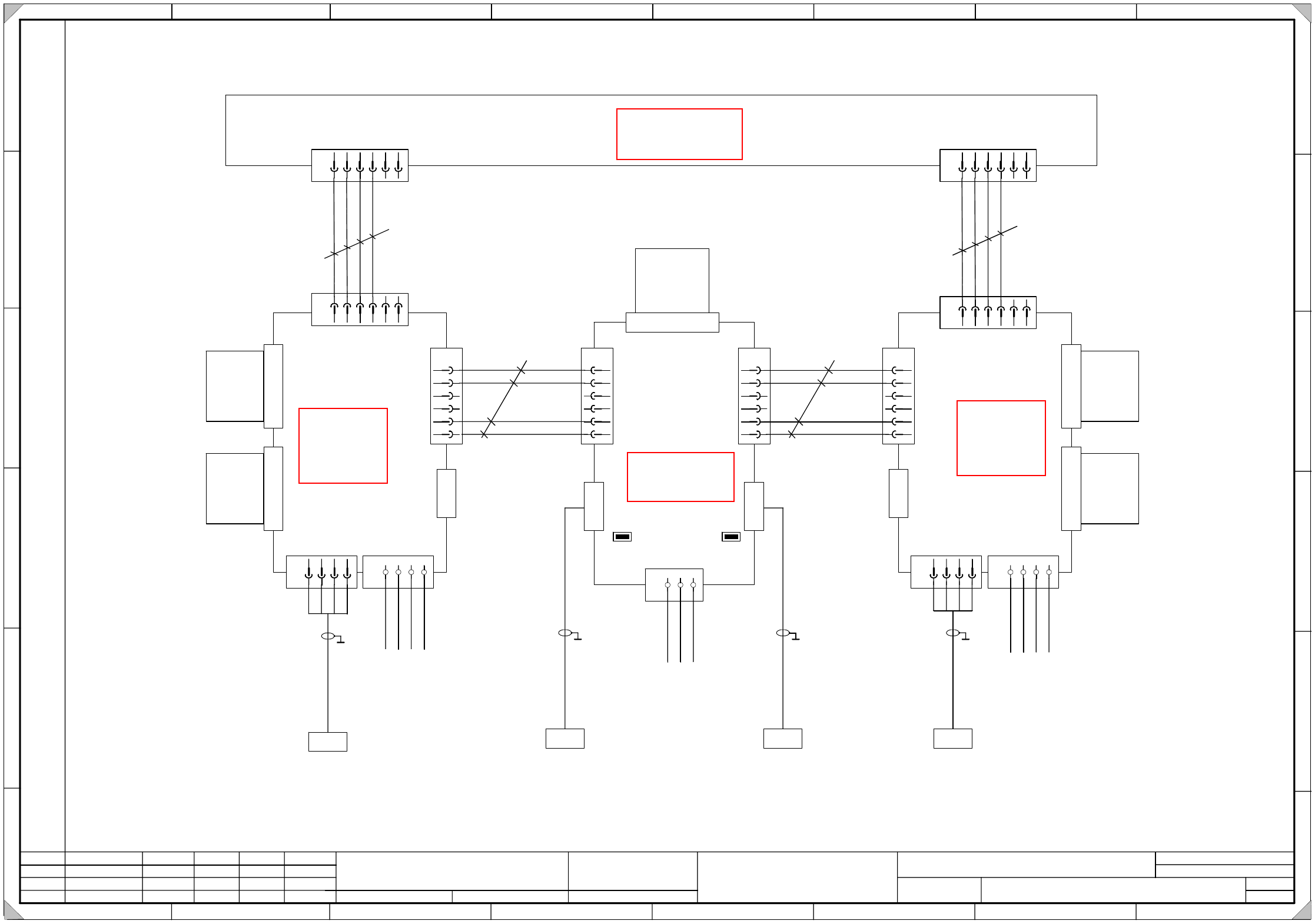
00354476-010301LD3 Servo unit, S-27 HM, basic module, wiring (sh. 2 of 5)
5
SIEMENS AG
PLEA1 E
Status Modified Date Name Standard Orig. Repl.f. Repl. by
Document status
Product status
Function status Date
Author
Check.
Sheet
Sh.
W
e
i
t
e
r
g
a
b
e
s
o
w
i
e
V
e
r
v
i
e
l
f
ä
l
t
i
g
u
n
g
d
i
e
s
e
r
U
n
t
e
r
l
a
g
e
,
V
e
r
-
w
e
r
t
u
n
g
u
n
d
M
i
t
t
e
i
l
u
n
g
i
h
r
e
s
I
n
h
a
l
t
s
n
i
c
h
t
g
e
s
t
a
t
t
e
t
,
s
o
w
e
i
t
n
i
c
h
t
a
u
s
d
r
ü
c
k
l
i
c
h
z
u
g
e
s
t
a
n
d
e
n
.
Z
u
w
i
d
e
r
h
a
n
d
l
u
n
g
e
n
v
e
r
-
p
f
l
i
c
h
t
e
n
z
u
S
c
h
a
d
e
n
e
r
s
a
t
z
.
A
l
l
e
R
e
c
h
t
e
v
o
r
b
e
h
a
l
t
e
n
,
i
n
s
b
e
s
o
n
d
e
r
e
f
ü
r
d
e
n
F
a
l
l
d
e
r
P
a
t
e
n
t
e
r
t
e
i
l
u
n
g
o
d
e
r
G
M
-
E
i
n
t
r
a
g
u
n
g
P
r
o
p
r
i
e
t
a
r
y
d
a
t
e
,
c
o
m
p
a
n
y
c
o
n
f
i
d
e
n
t
i
a
l
.
A
l
l
r
i
g
h
t
s
r
e
s
e
r
v
d
.
C
o
n
f
i
e
a
t
i
t
r
e
d
e
s
e
c
r
e
t
d
´
e
n
t
r
e
p
r
i
s
e
.
T
o
u
s
d
r
o
i
t
s
r
e
s
e
r
v
e
s
.
C
o
m
u
n
i
c
a
d
o
c
o
m
o
s
e
g
r
e
d
o
e
m
p
r
e
s
a
r
i
a
l
.
R
e
s
e
r
v
a
d
o
s
t
o
d
o
s
o
s
d
i
r
e
i
l
o
s
.
C
o
n
f
i
a
d
o
c
o
m
o
s
e
c
r
e
t
e
i
n
d
u
s
t
r
i
a
l
.
N
o
s
r
e
s
e
r
v
a
m
o
s
t
o
d
o
s
l
o
s
d
e
r
e
c
h
o
s
.
SIPLACE S27 HM SMD Placement System
Servo unit, basic module, wiring
A
B
C
D
E
F
1 2 3 4 5 6 7 8
1
2 3 4 5 6 7 8
A
B
C
D
E
F
3.
1.
1.
25.05.2000
17.07.2001
25.05.2000
Tuth
Tuth
Tuth 17.07.2001
Tuth
00354476-010301LD3
X
1
v
m
S
e
r
v
o
X
-
a
x
i
s
2
Backplane
X-axis 2
A23
(vm)
1234
X
7
v
m
X
6
v
m
1234
X
2
v
m
D
y
n
a
m
i
c
b
r
a
k
e
M
o
t
o
r
U
M
o
t
o
r
V
M
o
t
o
r
W
M
o
t
o
r
G
N
D
P
o
w
e
r
+
1
5
0
V
P
o
w
e
r
G
N
D
P
1
5
V
N
1
5
V
1
2
3
4
5
6
X4vm
A-GND
Tacho
A-GND
PTC
X
5
v
m
123456
A
-
G
N
D
T
a
c
h
o
m
e
t
e
r
A
n
t
i
-
c
r
a
s
h
P
1
5
V
X
3
v
m
k
e
y
key
1
2
3
4
5
6
X5vs
A-GND
PTC
123
X
6
v
s
G
N
D
P
1
5
V
N
1
5
V
1
2
3
4
5
6
X4vs
Tacho_X_N
Tacho_X_P
A-GND
PTC
X
2
v
s
Backplane
Tachometer analysis
A30
(vs)
X1vs
Tachometer
X / Y
X
1
v
n
S
e
r
v
o
Y
-
a
x
i
s
2
Backplane
Y-axis 2
A24
(vn)
X
5
v
n
123456
1234
X
7
v
m
X
6
v
m
1234
1
2
3
4
5
6
X4vn
X
2
v
n
D
y
n
a
m
i
c
b
r
a
k
e
X
3
v
n
M
o
t
o
r
U
M
o
t
o
r
V
M
o
t
o
r
W
M
o
t
o
r
G
N
D
P
o
w
e
r
+
1
5
0
V
P
o
w
e
r
G
N
D
P
1
5
V
N
1
5
V
A-GND
Tachometer
A-GND
PTC
A
-
G
N
D
T
a
c
h
o
C
r
a
s
h
P
1
5
V
k
e
y
key
X
1
1
d
123456
T
a
c
h
o
m
e
t
e
r
-
T
a
c
h
o
m
e
t
e
r
+
A
n
t
i
-
c
r
a
s
h
P
1
5
V
X
1
1
c
123456
T
a
c
h
o
m
e
t
e
r
-
T
a
c
h
o
m
e
t
e
r
+
A
n
t
i
-
c
r
a
s
h
P
1
5
V
S
t
a
r
p
o
i
n
t
0
0
9
0
0
3
5
4
4
7
2
-
x
x
X31b
y
e
/
g
n
b
r
b
l
b
k
S
t
a
r
p
o
i
n
t
0
0
7
P
o
w
e
r
s
u
p
p
l
y
u
n
i
t
+
1
5
V
v
i
o
P
o
w
e
r
s
u
p
p
l
y
u
n
i
t
-
1
5
V
w
h
p
k
b
k
p
k
g
y
0.25mm
2
ye/bk
0.25mm
2
wh
0.25mm
2
wh
S
t
a
r
p
o
i
n
t
0
0
7
P
o
w
e
r
s
u
p
p
l
y
u
n
i
t
+
1
5
V
P
o
w
e
r
s
u
p
p
l
y
u
n
i
t
-
1
5
V
w
h
p
k
b
k
p
k
g
y
S
t
a
r
p
o
i
n
t
0
0
9
S
t
a
r
p
o
i
n
t
0
0
7
P
o
w
e
r
s
u
p
p
l
y
u
n
i
t
+
1
5
V
v
i
o
P
o
w
e
r
s
u
p
p
l
y
u
n
i
t
-
1
5
V
w
h
p
k
b
k
p
k
g
y
0
0
3
5
4
4
7
4
-
x
x
X36ba
y
e
/
g
n
b
r
b
l
b
k
Anti-crash board
X
3
v
s
0
0
3
5
4
4
1
8
-
x
x
X32b
0
0
3
5
4
4
2
0
-
x
x
X38ba
0.25mm
2
ye/bk
key
key
Tacho_Y_N
Tacho_Y_P
2
Please note !
Insert jumpers J1 and J2 on the backplane for the tachometer analysis of gantry 2 ( A30 vs).
(This way, the sense of rotation and the tachometer voltage is adjusted.)
J1 J2
analysis
See page 5-5
See page 5-26
See page 5-26
See page 5-27
3 - 11
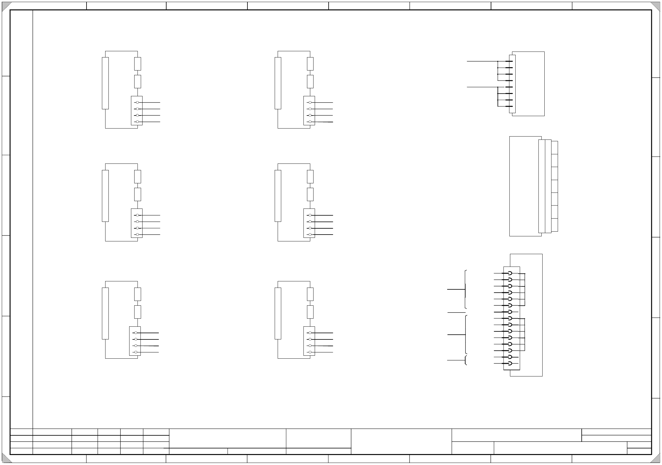
00354476-010301LD3 Servo unit, S-27 HM, basic module, wiring (sh. 3 of 5)
5
SIEMENS AG
PLEA1 E
Status Modified Date Name Standard Orig. Repl.f. Repl. by
Document status
Product status
Function status Date
Author
Check.
Sheet
Sh.
W
e
i
t
e
r
g
a
b
e
s
o
w
i
e
V
e
r
v
i
e
l
f
ä
l
t
i
g
u
n
g
d
i
e
s
e
r
U
n
t
e
r
l
a
g
e
,
V
e
r
-
w
e
r
t
u
n
g
u
n
d
M
i
t
t
e
i
l
u
n
g
i
h
r
e
s
I
n
h
a
l
t
s
n
i
c
h
t
g
e
s
t
a
t
t
e
t
,
s
o
w
e
i
t
n
i
c
h
t
a
u
s
d
r
ü
c
k
l
i
c
h
z
u
g
e
s
t
a
n
d
e
n
.
Z
u
w
i
d
e
r
h
a
n
d
l
u
n
g
e
n
v
e
r
-
p
f
l
i
c
h
t
e
n
z
u
S
c
h
a
d
e
n
e
r
s
a
t
z
.
A
l
l
e
R
e
c
h
t
e
v
o
r
b
e
h
a
l
t
e
n
,
i
n
s
b
e
s
o
n
d
e
r
e
f
ü
r
d
e
n
F
a
l
l
d
e
r
P
a
t
e
n
t
e
r
t
e
i
l
u
n
g
o
d
e
r
G
M
-
E
i
n
t
r
a
g
u
n
g
P
r
o
p
r
i
e
t
a
r
y
d
a
t
e
,
c
o
m
p
a
n
y
c
o
n
f
i
d
e
n
t
i
a
l
.
A
l
l
r
i
g
h
t
s
r
e
s
e
r
v
d
.
C
o
n
f
i
e
a
t
i
t
r
e
d
e
s
e
c
r
e
t
d
´
e
n
t
r
e
p
r
i
s
e
.
T
o
u
s
d
r
o
i
t
s
r
e
s
e
r
v
e
s
.
C
o
m
u
n
i
c
a
d
o
c
o
m
o
s
e
g
r
e
d
o
e
m
p
r
e
s
a
r
i
a
l
.
R
e
s
e
r
v
a
d
o
s
t
o
d
o
s
o
s
d
i
r
e
i
l
o
s
.
C
o
n
f
i
a
d
o
c
o
m
o
s
e
c
r
e
t
e
i
n
d
u
s
t
r
i
a
l
.
N
o
s
r
e
s
e
r
v
a
m
o
s
t
o
d
o
s
l
o
s
d
e
r
e
c
h
o
s
.
SIPLACE S27 HM SMD Placement System
Servo unit, basic module, wiring
A
B
C
D
E
F
1 2 3 4 5 6 7 8
1
2 3 4 5 6 7 8
A
B
C
D
E
F
3.
1.
1.
25.05.2000
17.07.2001
25.05.2000
Tuth
Tuth
Tuth 17.07.2001
Tuth
00354476-010301LD3
B
a
c
k
p
l
a
n
e
d
p
1
-
a
x
i
s
(
G
a
n
t
r
y
1
)
X
1
v
f
A20
X
3
v
f
X
2
v
f
B
a
c
k
p
l
a
n
e
z
-
a
x
i
s
(
G
a
n
t
r
y
1
)
X
1
v
d
A21
X
3
v
d
X
2
v
d
B
a
c
k
p
l
a
n
e
S
t
a
r
a
x
i
s
(
G
a
n
t
r
y
1
)
X
1
v
c
A22
X
3
v
c
X
2
v
c
B
a
c
k
p
l
a
n
e
S
t
a
r
a
x
i
s
(
G
a
n
t
r
y
2
)
X
1
v
o
A27
X
3
v
o
X
2
v
o
B
a
c
k
p
l
a
n
e
d
p
1
-
a
x
i
s
(
G
a
n
t
r
y
2
)
X
1
v
r
A25
X
3
v
r
X
2
v
r
B
a
c
k
p
l
a
n
e
z
-
a
x
i
s
(
G
a
n
t
r
y
2
)
X
1
v
p
A26
X
3
v
p
X
2
v
p
P
o
w
e
r
s
u
p
p
l
y
u
n
i
t
+
/
-
1
5
V
A17
1L-
4
6
8
10
12
14
16
18
20
22
24
26
28
30
32
6L+
-15V
-15V
-15V
-15V
-15V
-15V
1L-
+15V
+15V
+15V
+15V
+15V
+15V
Input
Output
X12
B
a
l
l
a
s
t
c
i
r
c
u
i
t
X13
A16
a2
a4
a6
a8
Star point 007 1L-
c2
c4
c6
c8
Star point 009 1L+
1
2
3
4
X
4
v
f
1L- Star point 007
6L+ Star point 002
+15V X12-Pin 6
-15V X12-Pin 20
(vf)
1
2
3
4
X
4
v
c
1L- Star point 007
2L+/5L+ Star point 001
+15V X12-Pin 6
-15V X12-Pin 20
(vd)
1
2
3
4
X
4
v
d
1L- Star point 007
6L+ Star point 002
+15V X12-Pin 6
-15V X12-Pin 20
(vc)
1
2
3
4
X
4
v
r
1L- Star point 007
6L+ Star point 002
+15V X12-Pin 10
-15V X12-Pin 24
(vr)
(vp)
1
2
3
4
X
4
v
o
1L- Star point 007
2L+/5L+ Star point 001
+15V X12-Pin 10
-15V X12-Pin 24
(vo)
1
2
3
4
X
4
v
p
1L- Star point 007
6L+ Star point 002
+15V X12-Pin 10
-15V X12-Pin 24
3
Output
Input
A
n
t
i
-
c
r
a
s
h
b
o
a
r
d
X
1
A15
X
1
1
X
1
1
b
X
1
1
a
X
1
1
c
X
1
1
d
X
1
1
e
X
1
1
f
X
1
1
g