00198481-01_Technical_Training_E_by_DEK_EN - 第21页
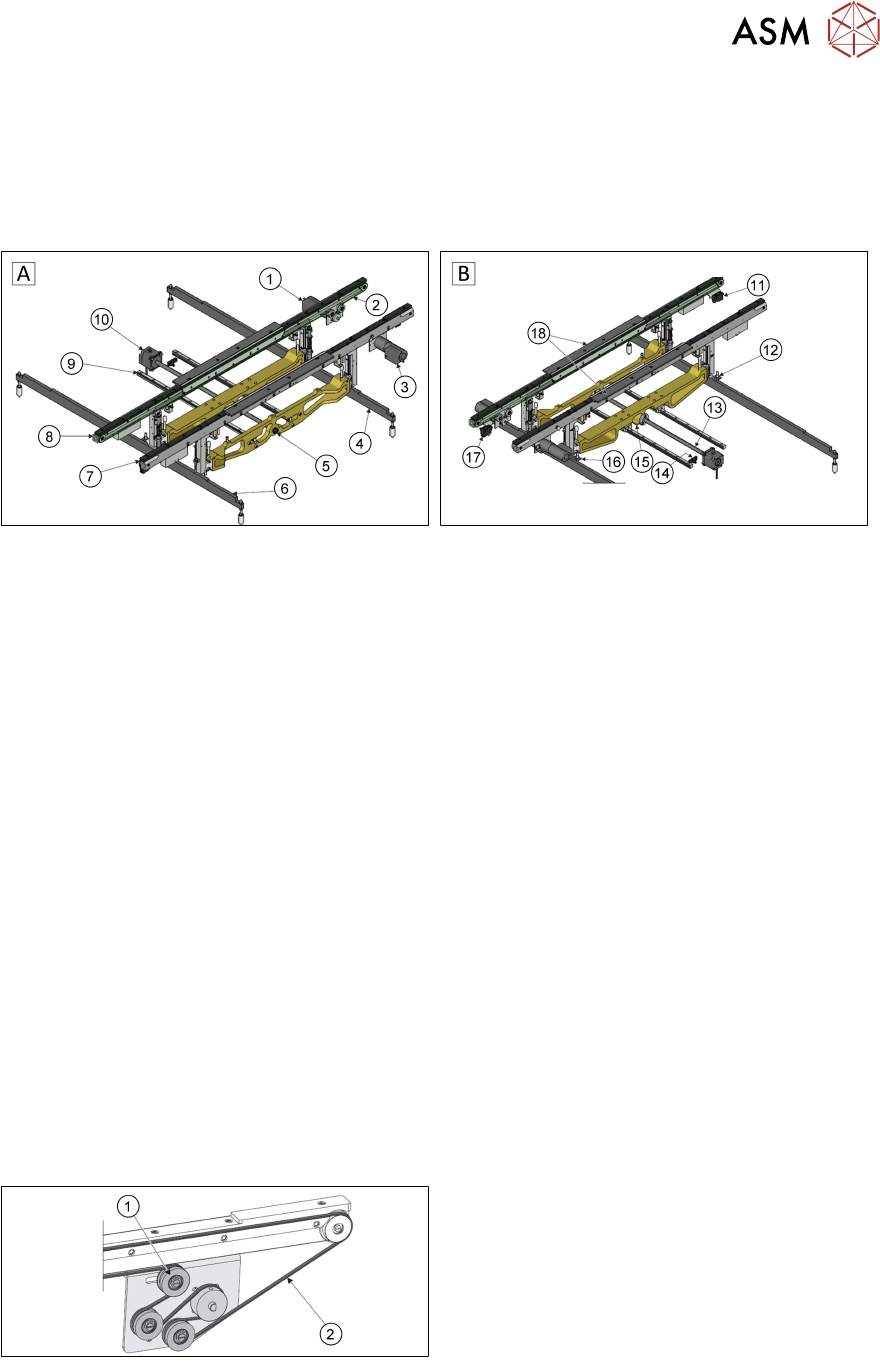
4 Conveyor System 4.1 Main Overview Technical Training E by DEK 12/2017 21 4 Conveyor System 4.1 Main Overview Transport Rail Style 2 A - View on Front B - View on Rear 1. Rear Transport Belt Drive Motor 11. Board at Lef…

3 Setting up the Machine
Room for Your Sketches and Notes
20 Technical Training E by DEK 12/2017
4 Conveyor System
4.1 Main Overview
Technical Training E by DEK 12/2017 21
4 Conveyor System
4.1 Main Overview
Transport Rail Style 2
A - View on Front B - View on Rear
1. Rear Transport Belt Drive Motor 11. Board at Left Sensor
2. Transport Belt (2 positions) 12. Left Rail Lift Sensor
3. Front Transport Belt Drive Motor 13. Rail Width Leadscrew
4. Right Hand Clatter Bar 14. Moving Rail Home Sensor
5. Manual Rail Adjuster 15. Moving Rail Home Vane
6. Left Hand Clatter Bar 16. Right Rail Lift Sensor
7. Fixed Front Rail 17. Board at Right Sensor
8. Moving Rear Rail 18. Board Clamps
9. Moving Rear Rail Linear Guide (2 positions)
10. Rail Width Drive Motor
4.2 Conveyor Functionality
The system has a programmable width conveyor system, set by the board width parameter, in the
product file. The rails transport the board, using belts, from the upline machine into the printer,
where the board is positioned, clamped, and printed. After printing, the board is transferred, using
the same belts, to the downline machine.The heavyboard option is available for heavy substrates.
This can transport substrates up to 6kg and for this purpose is equipped with special bearings and
transport belts (flat belts).
An option is available for heavy boards; the transport rails can transport boards weighing up to 6kg.
This is achieved using an extra drive pulley on each rail and flat profiled transport belts.
1. Tension pulley
2. Flat profiled transport belt
4 Conveyor System
4.2 Conveyor Functionality
22 Technical Training E by DEK 12/2017
NOTICE
Prevent damage to the camera board stop
To prevent damage to the camera board stop, the remote board stop must be used for
product boards over 1kg in weight. Information on the remote board stop is detailed in the
Raising Table chapter of this manual.
Sensor and Motors
A - Front view of the rail system
1. Left transport leg
2. Linear bearing
3. Right transport leg
4. Rear rail
B - Detailed view on arrow (A picture above)
5. Sensor LED
6. Sensor support bracket
7. Sensor
8. Rail stop bar (Clatter Bar)
9. Shock absorber
a. GO
b. NO GO
The rail lifted sensors are designed as a proximity switch in the current design. These are set as
described above. For detailed information please refer to the reference manual.
1. Test LED
2. SensitivitycControl
The input and output sensors on the transport line are optical sensors. The sensitivity is set on the
potentiometer. If a substrate is detected, the indicator lights up yellow. A blinking indicator is a
weak signal.
The transport system is equipped with one DC motor per rail.
The input and output sensors on the transport line are optical sensors. The sensitivity is set on the
potentiometer. If a substrate is detected, the indicator lights up yellow. A blinking indicator is a
weak signal.